Daktronics AB-1600-1.5,2.5 User Manual
Page 29
Electrical Installation
3-13
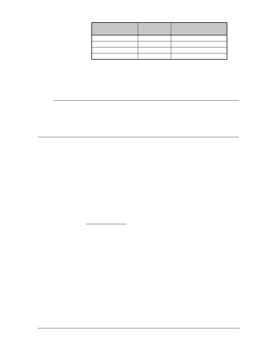
Temperature
Sensor
Field
Cabling
Controller Terminal
Block (TB7)
+V
Red
Pin 7 (+5V)
GND
Black
Pin 8 (GND)
P
Green
Pin 5 (Temp-P)
N
White
Pin 6 (Temp-N)
If using the same temperature sensor to control multiple displays, connect the signal
wire (P & N) to additional displays.
iWarning:
Do not connect +5V and GND to additional displays!
3.11.2 Venus 4600 System
Refer to Venus 4600 Installation/Operation Manual (ED-4602) for photo/temp
Sensor Installation.
3.12 First Time Turn On
After all connections are made, it is time to turn on the display for the first time field test.
1. Remove the fuses from the power termination panel.
2. Turn power ON to the display.
3. Carefully check the voltage between the hot lines and neutral. The normal voltage
range is between 120VAC and 125VAC. Refer to Section 3.8 for voltage
considerations.
4. If there are problems with voltage, check with your local electrician or power
company. Refer to Section 3.9.1.
5. Turn the power OFF and replace the fuses and covers of the termination panels.
Fasten the display modules back in place.
6. Turn power ON to the display.
7. The controller will do a power up test, displaying the following:
Venus 1500 System:
1. Output Test (DDD’s)
2. Product Name (Galaxy)
3. Display Size (Row x Column)
4. Firmware Number (ED-10134)
5. Firmware Revision (Rev X.XX)
6. COM1 Configuration (C1: V15/RTD)
7. COM2 Configuration (C2: None)
8. Line Frequency (60 Hz)
9. Hardware Address (HW: XX)
10. Software Address (SW: XX)
11. Display Name
12. Modem if present (Modem)