Daktronics AB-1600-1.5,2.5 User Manual
Page 28
3-12 Electrical
Installation
3.10 Dimming
For outdoor Starburst technologies, the display can be dimmed and brightened manually.
This can also be done under the BRIGHTNESS menu through the Automatic option (if there
is a light detector with the display). At a certain level of ambient lighting, the lamps will dim.
During the day time, the lamps should be brightest because they are competing with sunlight.
In the evening and at night, they should be dimmer because they are not competing with
sunlight. If a light detector is not present, make sure that the controller is set to have manual
brightness during daylight hours or control the dimming level through scheduling.
To change the dimming, refer to the software operator’s manual (Venus 1500, ED 9067;
Venus 4600, ED 4602).
3.10.1 Light Detector Installation - Venus 1500
Refer to Appendix A for light detector mounting instructions.
A light sensor can be easily connected to the display controller as follows:
1.
Route the light detector cable (Daktronics part number W-1234) through
conduit and into the display.
2.
Continue the cable into the controller box fitting labeled “LIGHT.”
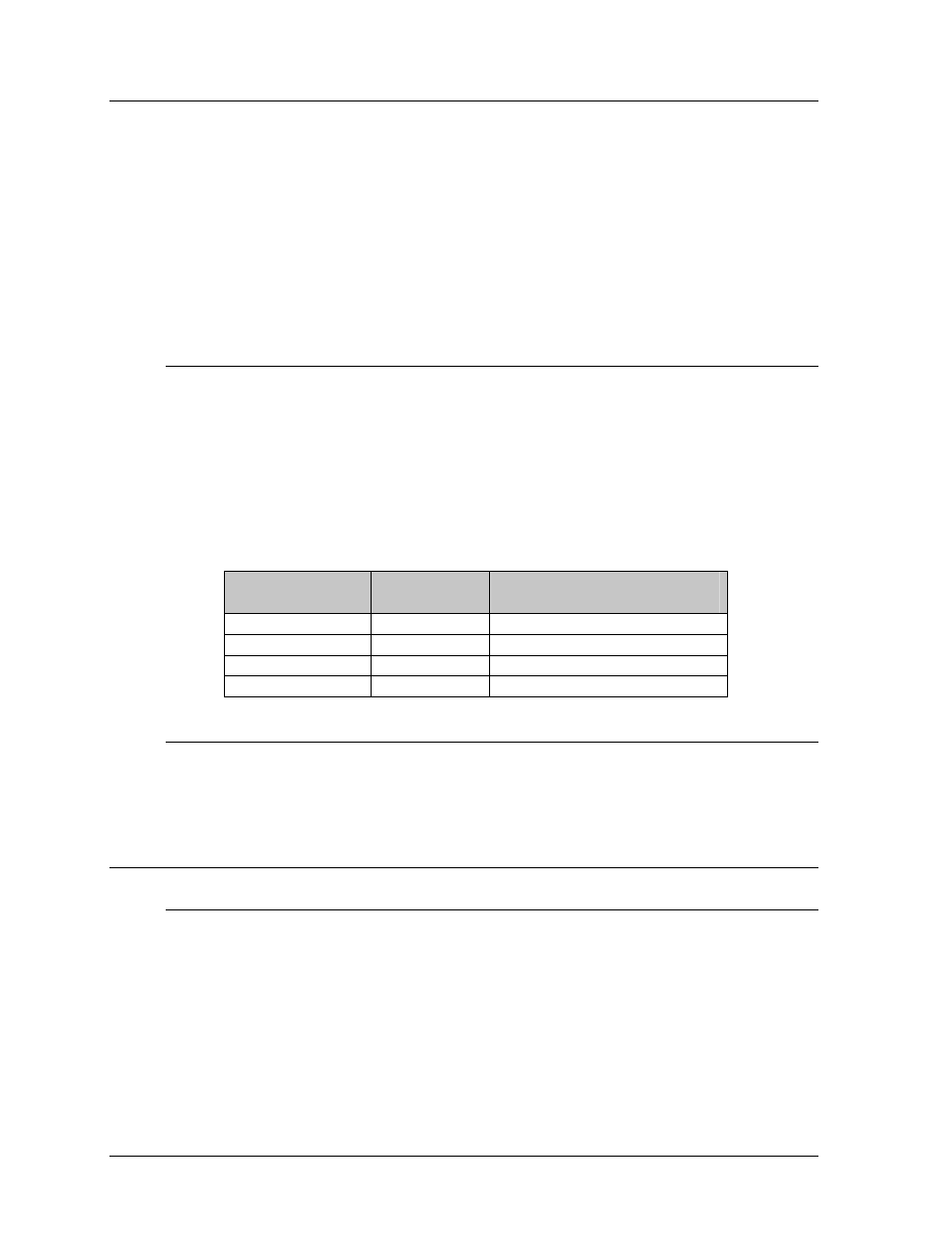
3. Strip the insulation and terminate wires to TB7 as shown below. Refer to
Section 4.6.1 for the location on TB7.
Light
Detector
Field
Cabling
Controller Terminal
Block (TB7)
+V
Red
Pin 1 (+5V)
GND
Black
Pin 2 (GND)
P
Green
Pin 3 (Light - P)
N
White
Pin 4 (Light - N)
3.10.2 Photo/Temp Sensor Installation - Venus 4600
Refer to Venus 4600 Installation/Operation Manual (ED-4602) for photo/temp
sensor
installation.
3.11 Temperature Sensor
3.11.1 Venus 1500 System
Refer to Appendix A for sensor mounting instructions.
A temperature sensor can be connected to the display controller as follows:
1.
Route the temperature sensor cable (Daktronics part number W-1234)
through conduit and into the display.
2.
Continue the cable into the controller box fitting labeled “TEMP.”
3. Strip the insulation and terminate wires to TB7 as shown in the following
table. Refer to Section 4.6.1 for the location on TB7.