Daktronics AB-1600-1.5,2.5 User Manual
Page 22
Electrical Installation
3-6
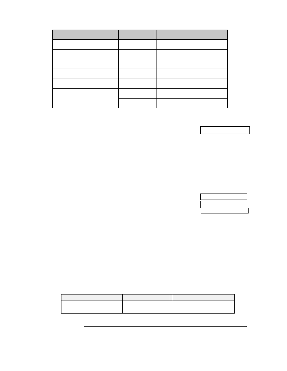
Signal Converter (J4/J5)
Field Cabling
Terminal Block (RS422 In)
Pin 1 (GND)
Red
Pin 1 (GND)
Pin 2 (RX-P)
Black
Pin 2 (TX-P)
Pin 3 (RX-N)
Brown
Pin 3 (TX-N)
Pin 4 (TX-P)
White
Pin 4 (RX-P)
Pin 5 (TX-N)
Blue
Pin 5 (RX-N)
Green
Pin 6 (GND)
Pin 6 (GND)
Shield (Bare)
N.C.
3.5.3 Modem (Venus 1500 System)
Reference
Drawing: Sys. Riser Diag. (Modem) .... Drawing A-103725
Route conduit and telephone cable to the left end of the master display.
Continue cable into controller box fitting labeled “Signal In.” Remove the
telephone terminal block cover and connect wire using standard telephone
wire colors. Replace the cover. Plug the short telephone RJ-11 cable into the
block and into the phone in RJ-11 jack of the modem board (refer to
Drawing A-103727 and A-103725).
3.5.4 Fiber
Reference Drawing: Sys. Riser Diag. (Fiber) ........ Drawing A-103730
Sys. Riser Diag. (S.L.I.) ....... Drawing A-103731
S.L.I. Signal Terminations .... Drawing A-103740
Route conduit and fiber cable from the PC to the left end of the master
display. Continue fiber to the controller box. Refer to proper section below.
Maximum fiber optic cable run should not exceed 2000 feet.
3.5.4.1 Venus 1500 System
Route fiber into controller box fitting labeled signal in. Terminate
fiber. Plug fiber ends into RX In and TX IN as shown in Drawing
A-103727 in Section 3.5.1. Terminate fiber at PC and plug
corresponding colors into signal converter (Daktronics Part Number
0A-1127-0239) as shown below:
PC Fiber Converter
Field Fiber
Display Controller
J3(RX-OUT)
J2(TX-OUT)
------------------
------------------
J4(TX2-IN)
J5(RX2-IN)
3.5.4.2 Venus 4600 System
Route fiber into serial line interface box and terminate fiber. Plug
fiber into J8 (RX). Refer to Drawings A-103731 and A-103740.