Mounting the vortek hoist – Daktronics Hoist Installation Manual User Manual
Page 10
8
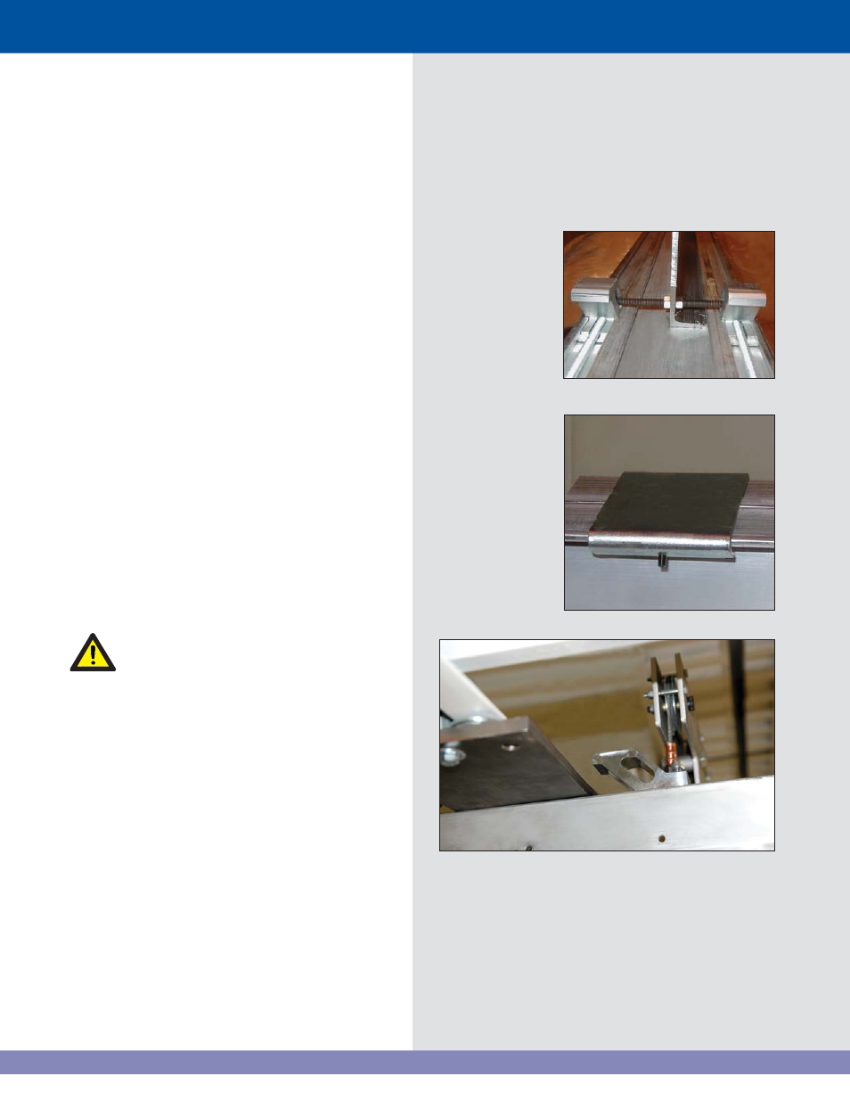
3. Tighten both nuts onto the backbone
stiffener as shown. Make sure the threaded
rod is centered across the backbone so
that it does not stick out of either side of
the beam clamps (Figure 16).
If the beam clamps on the power panel
end of the hoist are installed in the very
fi rst position, the installation blocks and
lifting clips may have to be used on the
inside of the support I-beams. In this
situation, the backbone stiffeners will have
to be installed after the hoist is lifted and
partially clamped in place.
4. To hold the tops of the backbone stiffeners
together, place a clamp onto a single side
and slide it 6" past the end of the second
channel. Repeat for the other end of the
stiffeners with the 2nd clamp (Figure 17).
Do not tighten the set screw on these clamps at
this time.
Mounting the Vortek Hoist
The hoist weighs approximately 650 lb
(295 kg) out of the crate. Take precautions
when lifting, making sure that the area is
roped off and unnecessary personnel are
away from the area.
•
Once the installation blocks are mounted and
tightened and the hoist lifting clips are securely
in place on the hoist backbone, lift the hoist
out the skid just a few inches.
•
Double check that all connections are secure
at the installation blocks and hoist lifting clips.
Make sure that the cables do not get caught
on anything as the hoist is raised.
•
When lifting the hoist to the level of the
I-beams, stop just short so that the beam
clamps can be adjusted for the spacing
of the I-beams (Figure 18). Raise the
hoist into position so the backbone is
about 1/2" below the I-beams and start
tightening the clamps using the 9/16"
socket and cordless drill set at MINIMUM
torque.
Figure 16: Tighten both nuts to backbone
stiffener
Figure 17: Clamp on backbone stiffener
Figure 18: Clamp on I-beam