Daktronics Hoist Installation Manual User Manual
Page 11
9
INSTALLATION
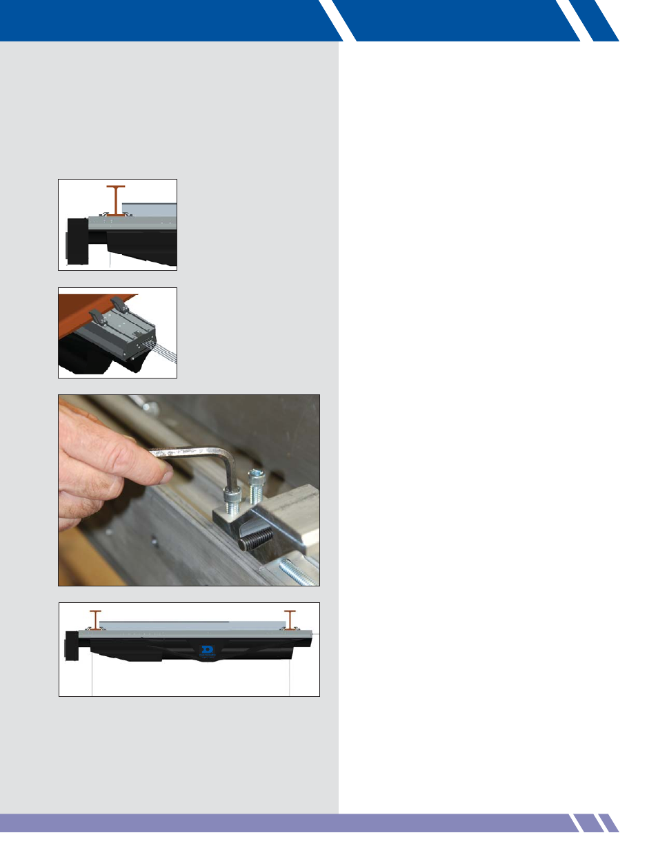
Figure 20:
Beam clamps
Figure 21: Tighten clamps to the backbone
Figure 19: Secure I-beam clamps
Figure 22:
Installed hoist
Tighten the clamps until they just contact
the top of the lower fl ange of the I-beam.
At this point, the lifting cables can be
slackened slightly. It is helpful to use a
cordless drill with a wobble extension drive
and socket to tighten beam clamps. Spread
a light lubricant on the bolt threads and
channels before tightening the bolts.
•
Confi rm the placement of the hoist, and
make any fi nal adjustments by sliding the
hoist upstage or downstage on the I-beam
as needed.
For some installations, this may be the
technique needed to fi t hoists into areas
without enough room to use the installation
blocks.
If the backbone stiffeners were not
installed earlier, please do so now.
•
With placement confi rmed, tighten the
beam clamps fi rst by alternating between
the two clamps until the hoist backbone
is contacting the I-beam. Repeat for the
onstage set of beam clamps (Figures 19
and 20).
•
Tighten the beam clamp bolts to 17-20 ft/lb
maximum.
As the beam clamps are tightened, the
backbone stiffeners are drawn onto the
I-beam for additional support. The threaded
rod bends and applies constant pressure
to the backbone stiffeners to minimize
vibration and noise.
•
When all beam clamps are tightened and
torqued to the proper specifications, the
5/16 x 18 socket head screws on the
sliding beam clamps must be tightened
to 10 ft/lb, securing the clamps to the
backbone (Figure 21).
•
With the hoist in place on the I-beam,
tighten the set screws on the two backbone
stiffener clamps.
Upon completion, the installed Vortek hoist will
look similar to Figure 22.