Daktronics Hoist Installation Manual User Manual
Page 7
INSTALLATION
5
Figure 6
: Nameplate
Figure 7: Model number label
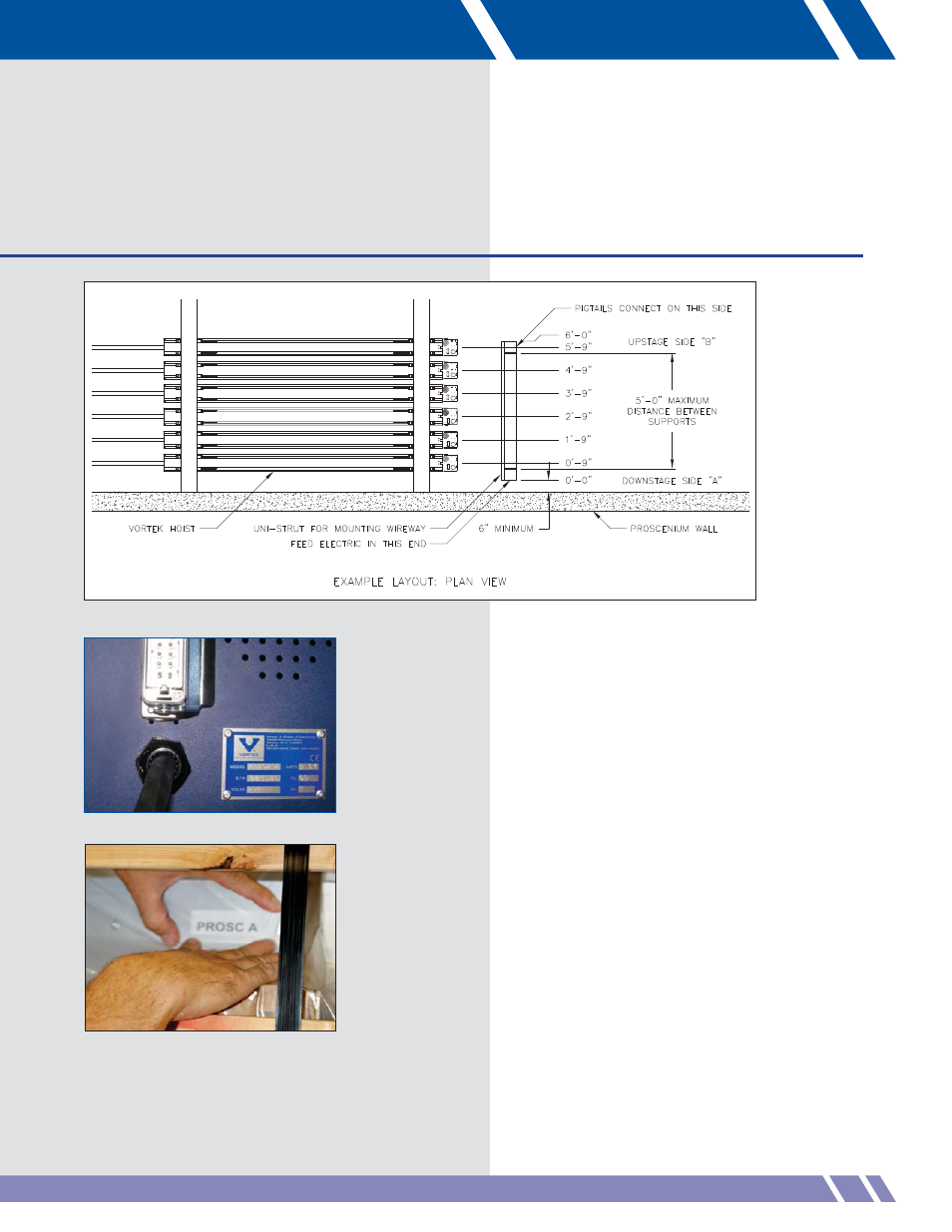
Figure 5:
Typical hoist layout
Follow the layout plan in order to place the crates
in the right position. Figure 5 shows one possible
way the Vortek hoists might be installed.
The layout, nameplate and label on the side of the
crate identify model number placement within the
installation.
Once out of the crate, Vortek Classic hoists are
virtually indistinguishable from each other except
for the nameplate on top of the electronics cabinet
(Figure 6).
Each hoist with Pro Series or M Series controller
has a pre-programmed network address and a
set number that is attached to the side of the hoist
(Figure 7). Please refer to the set plan layout for
the proper location.
If the wrong type of unit is installed in a
position that is specifi ed for another, it will
have to be uninstalled and moved to the
correct position.