Chapter 4 – DFI KS210-IMX6 Manual User Manual
Page 27
www.dfi .com
27
Chapter 4 Ports and Connectors
Chapter 4
Pins
Function
Pins
Function
1
GND
2
GND
3
LVDS1_Out3+
4
LVDS0_Out3+
5
LVDS1_Out3-
6
LVDS0_Out3-
7
GND
8
GND
9
LVDS1_Out2+
10
LVDS0_Out2+
11
LVDS1_Out2-
12
LVDS0_Out2-
13
GND
14
GND
15
LVDS1_Out1+
16
LVDS0_Out1+
17
LVDS1_Out1-
18
LVDS0_Out1-
19
GND
20
GND
21
LVDS1_Out0+
22
LVDS0_Out0+
23
LVDS1_Out0-
24
LVDS0_Out0-
25
GND
26
GND
27
LVDS1_CLK+
28
LVDS0_CLK+
29
LVDS1_CLK-
30
LVDS0_CLK-
31
GND
32
GND
33
TP_INT
34
TP_SCL
35
TP_VDD
36
TP_SDA
37
Backlight Power
38
Dimming
39
Backlight Power
40
Panel Power
The table below illustrates the pin functions of the LVDS LCD Panel connector:
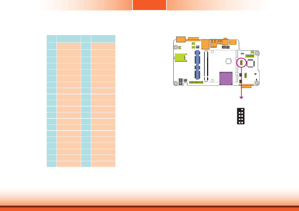
FlexCAN Connector
The CAN controller performs communication in accordance with the BOSCH CAN Protocol Ver-
sion 2.0B Active1 (standard format and extended format). The bit rate can be programmed to
a maximum of 1Mbit/s. To connect the CAN controller module to the FlexCAN connector, it is
necessary to add transceiver hardware.
When communicating in a CAN network, individual message objects are configured. The mes-
sage objects and the identifier masks for the receive filter for the received messages are
stored in the message RAM.
Controller Area Network is a message based protocol designed specifically for automotive ap-
plications but now is also used in other areas such as industrial automation and medical equip-
ment.
FlexCAN
1
2
9
N.C
N.C
N.C
N.C
N.C
N.C
CAN_LO
CAN_HI
GND