Chapter 4 – DFI KS210-IMX6 Manual User Manual
Page 30
www.dfi .com
30
Chapter 4 Ports and Connectors
Chapter 4
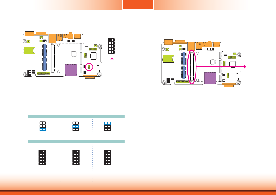
Serial (COM) Port
The system board is equipped with a 9-pin connector for connecting an external serial COM
port (COM 1). COM port 1 will vary according to JP4’s setting.
The serial COM port is RS232 asynchronous communication port with 16C550A-compatible
UARTs that can be used with modems, serial printers, remote display terminals, and other se-
rial devices. To connect COM 1, please refer to the following description. The serial port may
be mounted on a card-edge bracket. Install the card-edge bracket to an available slot at the
rear of the system chassis then insert the cable connector to the 9-pin connector. Make sure
the colored stripe on the ribbon cable is aligned with pin 1 of the connector.
1
2
9
COM 1:
RS232/422/485
JP4
RS232
RS422
Full Duplex
RS485
COM 1
1-2 On: RS232
(default)
1
3
5
2
4
6
3-4 On: RS422
Full Duplex
1
3
5
2
4
6
5-6 On: RS485
1
3
5
2
4
6
MXM Connector
The MXM connector is used to interface the carrier board with a Qseven board. Refer to the
table in the following pages for the pin functions of the MXM connector.
MXM
RXD
DCD-
TXD
DTR-
GND
DSR-
RTS-
CTS-
RI-
2 1
9
RXD-
RXD+
TXD+
TXD-
NC.
NC.
NC.
NC.
NC.
2 1
9
DATA-
DATA+
TXD
NC.
NC.
NC.
NC.
NC.
NC.
2 1
9