Mechanical diagram, Chapter 3 mechanical diagram – DFI CR900-B User Manual
Page 11
Advertising
www.dfi.com
Chapter 3 Hardware Installation
11
Chapter 3
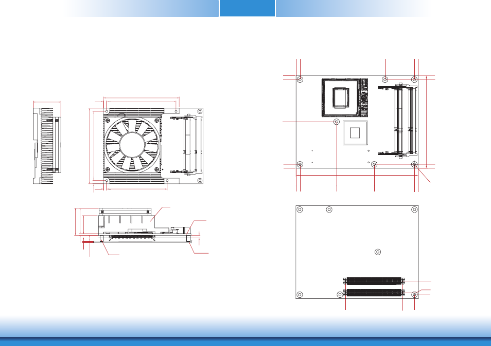
Mechanical Diagram
CR900-B Module with Heat Sink
Side View of the Module with Heat Sink and Carrier Board
CR900-B Module (Top View)
(Bottom View)
Ø2.70(*7 pcs)
Bottom View
Top View
0.00
0.
00
2.00
14.00
12.
50
70.
20
0.00
0.00
76.00
11
7.
00
0.00
4.00
121.00
4.
00
4.00
37
.4
1
43.67
87.00
91.00
4.00 0.00
87
.0
0
87.00
121.00
11
7.
00
91.00
125.00
95.00
4.00
87.00
95.00
4.00
87
.0
0
4.00
76.00
95.00
2.00
34
.7
0
24
.7
0
36
.7
0
Module PCB
The height of the
highest parts
3.50
1.60
5.0 or 8.0 mm
34.70
Cooler
Module PCB
CarrierBoard
standoff
Advertising