6 piping, Piping (4.6) – Flowserve PolyChem GRP User Manual
Page 17
USER INSTRUCTIONS POLYCHEM GRP ENGLISH 71569132 12-04A
Page 17 of 52
flowserve.com
b) The baseplate is leveled as necessary. Leveling
is accomplished by placing shims under the rails
of the base at the appropriate anchor bolt hole
locations. Levelness is checked in both the
longitudinal and lateral directions.
c) The motor and appropriate motor mounting
hardware is placed on the baseplate and the motor
is checked for any planar soft-foot condition. If any
is present it is eliminated by shimming
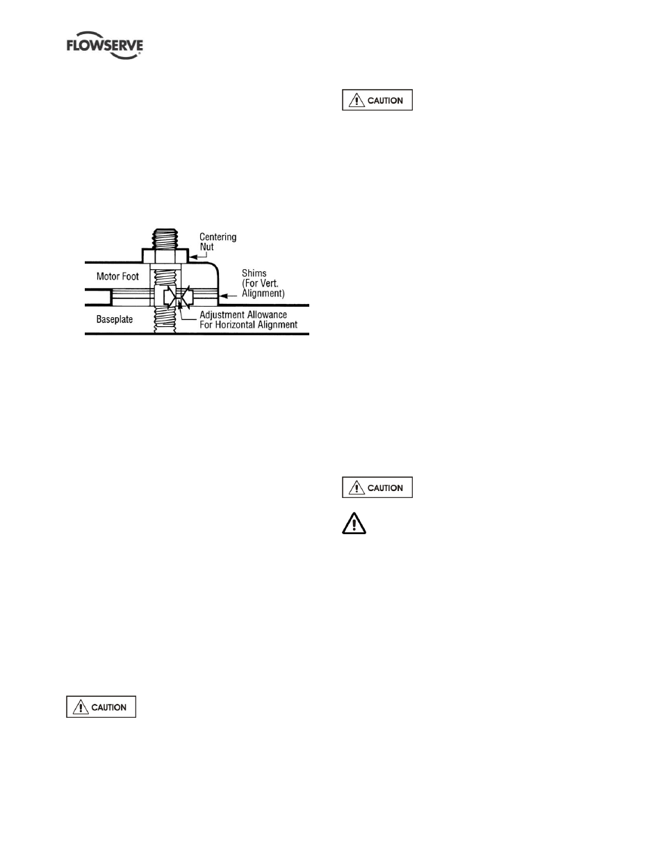
d) The motor feet holes are centered on the motor
mounting fasteners. This is done by using a
centering nut as shown in figure 4-6.
Figure 4-6
e) The motor is fastened in place by tightening the
nuts on two diagonal motor mounting studs.
f) The pump is put onto the baseplate and leveled.
The foot piece under the bearing housing is
adjustable. If an adjustment is necessary, add or
remove shims [109A] between the foot piece and
the bearing housing.
g) The spacer coupling gap is verified.
h) The parallel and angular vertical alignment is
made by shimming under the motor.
i)
The motor feet holes are again centered on the
motor mounting studs using the centering nut.
At this point the centering nut is removed and
replaced with a standard nut. This gives
maximum potential mobility for the motor to be
horizontally moved during final, field alignment.
All four motor feet are tightened down.
j)
The pump and motor shafts are then aligned
horizontally, both parallel and angular, by moving
the pump to the fixed motor.
k) The pump feet are tightened down.
l)
Both horizontal and vertical alignment is again
final checked as is the coupling spacer gap.
See section 4.8 for Final Shaft Alignment
4.6 Piping
Protective covers are fitted to the pipe
connections to prevent foreign bodies entering during
transportation and installation. Ensure that these
covers are removed from the pump before connecting
any pipes.
4.6.1 Suction and discharge pipework
Never use pump as a support for
piping.
All piping must be independently supported,
accurately aligned and preferably connected to the
pump by a short length of flexible piping. The pump
should not have to support the weight of the pipe or
compensate for misalignment. It should be possible
to install suction and discharge bolts through mating
flanges without pulling or prying either of the flanges.
All piping must be tight.
Pumps may air-bind if air is allowed to leak into the
piping. If the pump flange(s) have tapped holes,
select flange fasteners with thread engagement at
least equal to the fastener diameter, but that do not
bottom out in the tapped holes before the joint is tight.
Maximum forces and moments allowed on the pump
flanges vary with the pump size and type. To
minimize these forces and moments that may, if
excessive, cause misalignment, hot bearings, worn
couplings, vibration and the possible failure of the
pump casing, the following points should be strictly
followed:
Prevent excessive external pipe load
Never draw piping into place by applying force to
pump flange connections
Do not mount expansion joints so that their force,
due to internal pressure, acts on the pump flange
Ensure piping and fittings are flushed
before use.
Ensure piping for hazardous liquids is arranged
to allow pump flushing before removal of the pump.
The GRP suction and discharge flanges require full
flat face gaskets with a minimum thickness of 3.2 mm
(0.125 in.) and a hardness 70 durometer (Shore A).
Check that the gasket material is compatible with the
fluid and that the inner diameter of the gasket is
centered before assembly.
Use flat washers behind the pump flanges and do not
exceed 41 Nm (30 lbf
•ft) torque on the flange bolting.
4.6.2 Suction piping
To avoid NPSH and suction problems, suction piping
must be at least as large as the pump suction
connection. Never use pipe or fittings on the suction
that are smaller in diameter than the pump suction size.