8 disassembly, Disassembly (6.8), Dismantling (6.8, disassembly) – Flowserve PolyChem GRP User Manual
Page 35
USER INSTRUCTIONS POLYCHEM GRP ENGLISH 71569132 12-04A
Page 35 of 52
flowserve.com
Now, rotate the bearing carrier counter-clockwise to
get the proper clearance. Refer to figure 5-11 for the
proper impeller clearance. Rotating the bearing carrier
the width of one of the indicator patterns cast into the
bearing carrier moves the impeller axially 0.1 mm
(0.004 in.). (See figure 6-5.)
Determine how far to rotate the bearing carrier by
dividing the desired impeller clearance by 0.1 mm
(0.004 in.) (one indicator pattern). Tightening the set
screws [6570.3] will cause the impeller to move
0.05 mm (0.002 in.) away from the casing because of
the internal looseness in the bearing carrier threads.
This must be considered when setting the impeller
clearance. Rotate the bearing carrier counter-
clockwise the required amount to get the desired
clearance to the casing.
Lastly, uniformly tighten the set screws
[6570.3] in incremental steps up to the final torque
value to lock the bearing carrier in place.
See section 5.3 for impeller clearance settings.
6.8 Disassembly
6.8.1 Power end removal
a) Before performing any maintenance, disconnect the
driver from its power supply and lock it off line.
Lock out power to driver to
prevent personal injury.
b) Close the discharge and suction valves, and
drain all liquid from the pump.
c) Close all valves on auxiliary equipment and
piping, then disconnect all auxiliary piping.
d) Decontaminate the pump as necessary.
If Flowserve PolyChem pumps
contain dangerous chemicals, it is important to
follow plant safety guidelines to avoid personal
injury or death.
e) Remove the coupling guard. (See section 5.5.)
f) Remove the spacer from the coupling.
g) Remove casing fasteners [6570.1].
h) Remove the fasteners holding the bearing
housing foot to the baseplate.
i)
Move the power end, rear cover, and impeller
assembly away from the casing. Discard the
casing/cover O-ring [4610.1].
The power end and rear cover
assembly is heavy. It is important to follow plant
safety guidelines when lifting it.
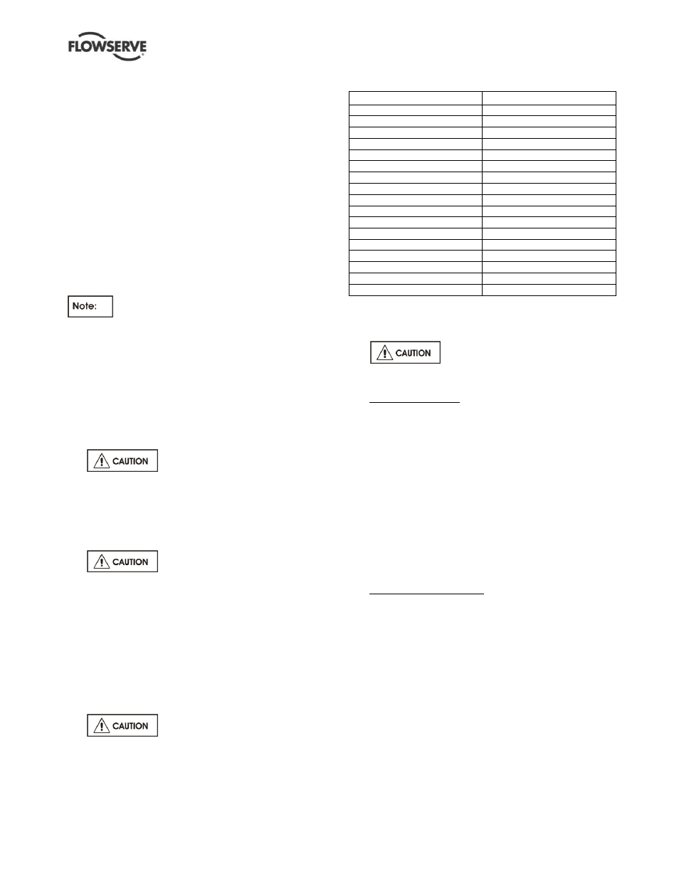
Figure 6-7
Pump size
Impeller fixing
1J1.5 x 1G - 6
Polygon
1J3 x 1.5G - 6
Threaded
1J3 x 2G - 6K
Polygon
1K3 x 2GS - 7
Threaded
1J1.5 x 1G - 8
Polygon
2K3 x 1.5G - 8
Polygon
2K3 x 2G - 8
Threaded
2K4 x 3G - 8
Polygon
2K2 x 1G - 10
Threaded
2K3 x 1.5G - 10
Polygon
2K4 x 3G - 10
Polygon
2K6 x 4G - 10
Polygon
2K3 x 1.5G - 13
Threaded
2K4 x 3G - 13
Threaded
3J8 x 6G - 13
Threaded
3J12 x 10G
– 15
Threaded
4J12 x 10G
– 15B
Threaded
6.8.2 Impeller removal
a) Remove the coupling hub from the pump shaft
[2100].
Do not apply heat to the impeller.
If liquid is entrapped in the hub, an explosion
could occur.
b) Threaded impellers. (See figure 6-7 and 6-8.) Use
a shaft key [6700] and mount the impeller wrench
from the Flowserve Mark 3 tool kit (figure
6-1) to the end of the shaft. With the wrench handle
pointing to the left when viewed from the impeller
end, grasp the impeller [2200] firmly with both
hands (wear heavy gloves). By turning the impeller
in the clockwise direction move the wrench handle
t
o the 11:00 o’clock position and then spin the
impeller quickly in a counter-clockwise direction so
that the wrench makes a sudden impact with a hard
surface on the bench. After several sharp raps, the
impeller should be free. Unscrew the impeller and
remove from the shaft. Discard the impeller-to-
sleeve gasket [4590.3].
c) Polygon drive impellers. (See figure 6-7.)
Unscrew impeller nose cone nut [2912] and
remove impeller nose cone nut gasket [4590.4].
d) Unscrew impeller stud [2913.1] on Group 1 units,
or impeller locknut [3712.2] and washer [6541.6]
on Group 2 units.
e) Rotate the bearing carrier [3240] counter clockwise
until the impeller makes contact with the rear cover
[1220]. Further rotation will completely loosen the
impeller from the shaft [2100].
f) Remove the impeller-to-sleeve gasket [4590.3].
g) If a cartridge type mechanical seal [153] is used
(see figure 6-9), the spacing clips or tabs should
be installed prior to loosening the set screws
which attach the seal to the shaft and before
removing it from the cover. This will ensure that
the proper seal compression is maintained.