Flowserve PolyChem GRP User Manual
Page 44
USER INSTRUCTIONS POLYCHEM GRP ENGLISH 71569132 12-04A
Page 44 of 52
flowserve.com
6.10.3 Impeller assembly
If a new impeller of maximum diameter has been
acquired and needs reducing, or if the existing
impeller diameter needs reducing, they must both be
machined down to the correct size. It is preferred to
send the impeller to your Flowserve representative
for machining, but when this is not possible, the
following procedure can be used:
a) Obtain the correct machining mandrel from your
Flowserve representative or use the pump shaft
and impeller bolting.
b) Carefully mount the mandrel or shaft in a lathe
suitable for machining GRP.
c) Mount the impeller and, using a dial indicator,
verify the outer diameter run-out and impeller
face run-out (on the vanes at the outer diameter)
are each less than 0.13 mm (0.005 in.) TIR.
d) Prepare to machine. All impellers are machined
straight across, parallel to the shaft except sizes
2K6x4G-10, 3J12x10G-15 and 4J12x10G-15B
which have angled cuts. The 2K6x4G-10 vanes
are machined at an angle of 15 degrees to the
shaft axis whilst the 3J12x10G-15 and
4J12x10G-15B vanes are machined at an angle
of 10 degrees to the shaft axis with the larger
diameter at the open vane face and the smaller
diameter at the back impeller shroud. The listed
impeller diameter is the mid-point of the vane.
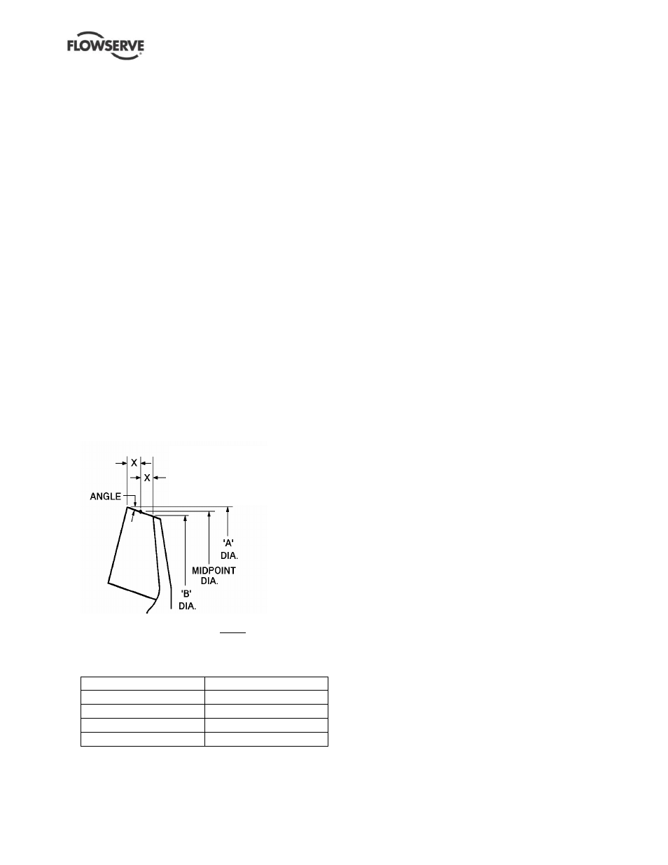
Refer to the sketch for these details:
Angle cut for sizes
2K6x4G-10,
3J12x10G-15
4J12x10G-15B
Midpoint (listed) diameter = A + B
2
Angle = 15 degrees (2K6x4G-10) or
10 degrees (3J12x10G-15 and 4J12x10G-15B)
Depth of cut, roughing
5.10 mm (0.200 in.)
Feed rate per revolution
0.38 mm (0.015 in.)
Depth of cut, finishing
0.51 mm (0.020 in.)
Feed rate per revolution
0.08 mm (0.003 in.)
Surface speed per minute
91 to 213 m (300 to 700 ft)
e) Machining the GRP material produces dust that can
be irritating to the operator, but is not hazardous.
Dust vacuum systems, skin protection and a dust
mask are recommended. A typical machining setup
would be as described below.
f) Start machining across the outer diameter.
Machine from both sides to the middle. Continue
with additional cuts until the required impeller
diameter is achieved.
g) The finished impeller can then be removed from the
lathe and installed in the pump. No mechanical
balancing or resin coating of the vane tips is required.
6.10.3.1 Polygon impeller drive units
a) Position the impeller to sleeve gasket [4590.3]
into the groove on the impeller and push impeller,
hand tight, onto the shaft. The impeller is a slight
interference fit with the shaft and its face should
extend 0.38 to 0.89 mm (0.015 to 0.035 in.) from
the end of the shaft.
b) Seat the impeller by fitting the impeller stud
[2913.1] on Group 1 and torque up to 27 Nm (20
lbf
•ft) or on Group 2 fit the washer [6541.6] and
locknut [3712.2] and torque up to 48 Nm (35
lbf
•ft). This will push the impeller face down until
it lines up with the end of the shaft.
c) Install the impeller nose cone nut gasket [4590.4]
on the impeller, fit the impeller nose cone [2912]
and tighten hand tight 3 Nm (2 lbf
•ft) as this nut
does not hold the impeller in place but merely
seals the shaft from the fluid.
6.10.3.2 Threaded impeller drive units
a) Position the impeller to sleeve gasket [4590.3]
into the groove on the sleeve or impeller.
b) Lubricate the impeller threads and pilot fit with
light oil having a light graphite suspension.
c) Locate the impeller on the shaft and thread on.
d) The impeller clearance should now be pre-set to
the tabulated dimensions in section 6.6.
6.10.4 Gland fastening to the cover
a) For mechanical seals, assemble the gland [4120]
onto the gland studs [6572], fit the gland backing
plate (if supplied), then fit the gland washers
[6541.5] and nuts [6580.2] and torque up evenly
to 7 Nm (5 lbf
•ft) on Group 1 units and 14 Nm
(10 lbf
•ft) on all other sizes.
b) For external seals, position the seal rotating
assembly against the seal stationary face,
compress the springs as specified on the seal
drawing and tighten the seal setscrews evenly.
c) For cartridge seals, tighten the setscrews evenly
and remove the gland centering tabs, but retain
for future maintenance.