Flowserve PolyChem GRP User Manual
Page 18
USER INSTRUCTIONS POLYCHEM GRP ENGLISH 71569132 12-04A
Page 18 of 52
flowserve.com
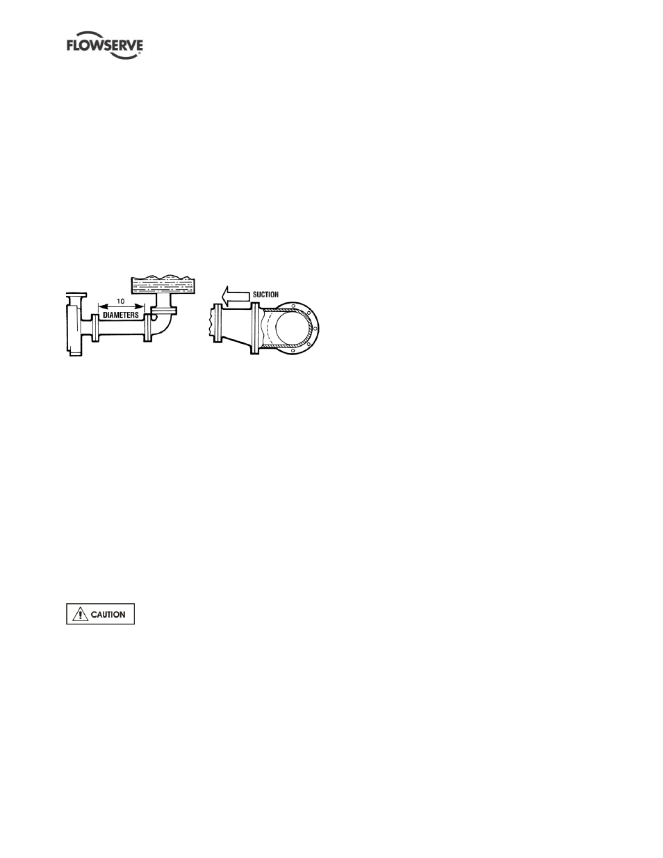
Figure 4-7 illustrates the ideal piping configuration
with a minimum of 10 pipe diameters between the
source and the pump suction. In most cases,
horizontal reducers should be eccentric and mounted
with the flat side up as shown in figure 4-8 with a
maximum of one pipe size reduction. Never mount
eccentric reducers with the flat side down.
Horizontally mounted concentric reducers should not
be used if there is any possibility of entrained air in
the process fluid. Vertically mounted concentric
reducers are acceptable. In applications where the
fluid is completely de-aerated and free of any vapor
or suspended solids, concentric reducers are
preferable to eccentric reducers
Figure 4-7 Figure 4-8
Avoid the use of throttling valves and strainers in the
suction line. Start up strainers must be removed
shortly before start up. When the pump is installed
below the source of supply, a valve should be
installed in the suction line to isolate the pump and
permit pump inspection and maintenance. However,
never place a valve directly on the suction nozzle of
the pump.
Refer to the Durco Pump Engineering Manual and
the Centrifugal Pump IOM section of the Hydraulic
Institute Standards for additional recommendations
on suction piping, section 10. Refer to section 3.4 for
performance and operating limits.
4.6.3 Discharge piping
Install a valve in the discharge line. This valve is
required for regulating flow and or to isolate the pump
for inspection and maintenance.
When fluid velocity in the pipe is high,
for example, 3 m/s (10 ft/sec) or higher, a rapidly
closing discharge valve can cause a damaging
pressure surge. A dampening arrangement should
be provided in the piping.
A non-return valve should be located in the discharge
pipework to protect the pump from excessive back
pressure and hence reverse rotation when the unit is
stopped.
4.6.4 Allowable nozzle loads - PolyChem GRP
pumps (ASME B73.5)
Flowserve chemical process pumps meet or exceed
the allowable nozzle loads given by ANSI/HI 9.6.2.
The following paragraphs describe how to calculate
the allowable loads for each pump type and how to
determine if the applied loads are acceptable.
The following steps are based upon ANSI/HI 9.6.2.
All information necessary to complete the evaluation
is given below. For complete details please review
the standard.
a)
Find the “Baseplate Correction Factor” in figure
4-10. The correction factor depends upon how
the baseplate is to be installed
b) The casing material correction factor for the GRP
material is 0.9.
c) Select the lowest correction factor from steps a)
and b). For example:
If the pump is mounted on a Type A grouted
baseplate, the correction factor used is 0.9.
If the pump is mounted on a Type D stilt
mounted baseplate, the correction factor is 0.75.
d) Locate the pump model being evaluated in
figures 4-12 through 4-15 and multiply each load
rating by the lowest correction factor. Record the
adjusted loads for each table.
e) Calculate the applied loads at the casing flanges
according to the coordinate system depicted in
figure 4-9. The 12 forces and moments possible
are Fxs, Fys, Fzs, Mxs, Mys, Mzs, Fxd, Fyd, Fzd,
Mxd, Myd and Mzd. For example, Fxd
designates Force in the “x” direction on the
discharge flange. Mys designates the Moment
about the “y”-axis on the suction flange.
f) Figure 4-11 gives the acceptance criteria
equations. For long coupled pumps, equation
sets 1 through 5 must be satisfied.
g) Equation set 1. Each applied load is divided by
the corresponding adjusted figure 4-12 value.
The absolute value of each ratio must be less
than or equal to one.
h) Equation set 2. The summation of the absolute
values of each ratio must be less than or equal to
two. The ratios are the applied load divided by
the adjusted figure 4-13 values.
i)
Equation sets 3 and 4. These equations are
checking for coupling misalignment due to nozzle
loading in each axis. Each applied load is divided
by the corresponding adjusted load from figure 4-14
and 4-15. The result of each equation must be
between one and negative one.
j)
Equation set 5. This equation calculates the total
shaft movement from the results of equations 3 and
4. The result must be less than or equal to one.