5 tools required, 6 fastener torques, 7 disassembly – Flowserve WMV IDP User Manual
Page 18: Tools required (6.5)
WMV, WMVS USER INSTRUCTIONS ENGLISH 26999970 10-12
Page 18 of 28
flowserve.com
6.4.2.1 WMV rotating assembly
Stages
5WMV
8WMV
16WMV
4
RASSY-5WMV4-STD
RASSY-8WMV4
RASSY-16WMV4
5
RASSY-5WMV5
RASSY-8WMV5
RASSY-16WMV5
6
RASSY-5WMV6
RASSY-8WMV6
RASSY-16WMV6
8
RASSY-5WMV8-
STD
RASSY-8WMV8
RASSY-16WMV8
10
RASSY-5WMV10-
STD
RASSY-8WMV10
RASSY-16WMV10
12
RASSY-5WM12
RASSY-8WMV12-
STD
RASSY-16WMV12
14
RASSY-5WMV14
RASSY-8WM14
RASSY-16WMV14-
STD
16
RASSY-5WMV16
RASSY-8WMV16
RASSY-16WMV16
18
RASSY-5WMV18
RASSY-8WMV18
N/A
20
RASSY-5WMV20-
STD
RASSY-8WMV20
N/A
24
RASSY-5WMV24
RASSY-8WMV24-
STD
N/A
30
N/A
N/A
N/A
6.4.2.2 WMVS rotating assembly
Stages
5WMVS
8WMVS
16WMVS
4
RASSY-5WMVS4
RASSY-8WMVS4
RASSY-16WMVS4
5
RASSY-5WMVS5
RASSY-8WMVS5
RASSY-16WMVS5
6
RASSY-5WMVS6
RASSY-8WMVS6
RASSY-16WMVS6
8
RASSY-5WMVS8
RASSY-8WMVS8
RASSY-16WMVS8
10
RASSY-5WMVS10
RASSY-8WMVS10
RASSY-16WMVS10
12
RASSY-5WMVS12
RASSY-8WMVS12
RASSY-16WMVS12
14
RASSY-5WMVS14
RASSY-8WMVS14
RASSY-16WMVS14
16
RASSY-5WMVS16
RASSY-8WMVS16
RASSY-16WMVS16
18
RASSY-5WMVS18
RASSY-8WMVS18
RASSY-16WMVS18
20
RASSY-5WMVS20
RASSY-8WMVS20-
STD
RASSY-16WMVS20
24
RASSY-5WMVS24
RASSY-8WMVS24
RASSY-16WMVS24
30
RASSY-5WMVS20-
STD
RASSY-8WMVS30
N/A
6.5 Tools required
A typical range of tools that will be required to
maintain these pumps is listed below.
Readily available in standard tool kits, and dependent
on pump size:
Open ended spanners (wrenches) to suit up to
M 20 screws/nuts
Socket spanners (wrenches), up to M 20 screws
Allen keys, up to 10 mm (A/F)
Range of screwdrivers
Thickness feeler gauges
Shims of 1 mm thickness
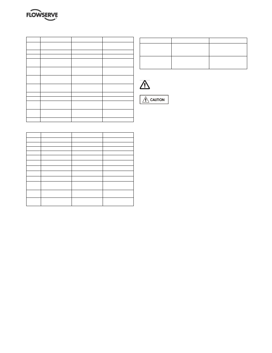
6.6 Fastener torques
Pump size
Fastener
Torque Nm (lbf
•ft)
5 and 8WMV(S)
Impeller nut
Tie rod nut
Coupling screw
13.5 (10)
35-40 (25-30)
27 (20)
16WMV(S)
Impeller nut
Tie rod nut
Coupling screw
20 (15)
55 (40)
27 (20)
6.7 Disassembly
Refer to Safety section before dismantling the
pump.
Before dismantling the pump for
overhaul, ensure genuine Flowserve replacement
parts are available. Refer to sectional drawings for
part numbers and identification. (See section 8, Parts
lists and drawings.)
a) Isolate the power supply and disconnect motor
cables.
b) Close suction and discharge valves and drain the
pump casing - remove drain plugs (22) and (23).
c) Pumps mounted horizontally must be removed
from the pipework and lifted to the vertical
position for dismantling purposes.
d) Spring out the coupling guards (5). Remove the
four socket head screws from the coupling and
separate the coupling halves.
e) Push out the location pin (4) from the pump shaft.
f)
Remove the four bolts securing the motor to the
motor stool and lift off the motor. (Tapped holes for
lifting eyes are incorporated in the larger motors.)
g) Remove the four tie rod nuts and lift off the motor
stool, withdraw the pre-load cone (9) and any
shims (10).
6.7.1 Mechanical seal
a) Without further dismantling this provides access
to the mechanical seal. Pumps are fitted with
either a Crane Type 502 seal (8) or Flowserve
PAC P250 seal (8). Pull off the mechanical seal
by hand or use light leverage if necessary.
Cleaning the shaft and lubrication by soap
solution or light oil is beneficial in this operation.
The seal seat is removed from the motor stool by
pressing out from the motor side.
b) If replacing the seal is the only maintenance
required, clean the pump shaft, replace the O-ring
in the motor stool, if damaged and re-assemble the
pump as described in the assembly section.
c) To continue dismantling, lift off the outer casing
(18), remove the tie rods (17), and release the seal
retaining ring (12) by slackening the grub screw
(11). (In the case of the older type Angus seal, the
sleeve is removed by slackening the grub screw.)