Flowserve WMV IDP User Manual
Page 20
WMV, WMVS USER INSTRUCTIONS ENGLISH 26999970 10-12
Page 20 of 28
flowserve.com
e) Lower the shaft and balance drum assembly, with
one impeller, into the suction/discharge casing
and stage piece adaptor. Ensure that the
impeller is sitting squarely on the top face of the
stage piece adaptor and fit the first stage piece
ensuring that the lug locates with the slot in the
stage piece adaptor.
f)
Now place shims, 1 mm (0.04 in.) thick, underneath
the first stage piece and then slide the next impeller
down the shaft into contact with the stage piece.
g) Keeping the shaft firmly pressed down, hand
tighten the impeller nut with a box spanner as
described above.
h) Now remove the 1 mm (0.04 in.) shims and
tighten the impeller nut to the torque listed.
i)
Holding down the stage piece with one hand
check that there is a minimum of 4 mm (0.16 in.)
axial movement (5 mm [0.2 in.] on size 16WMV)
in the shaft and impellers.
j)
Check the shaft for ease of rotation.
k) Fit each succeeding stage piece and impeller in
the same manner, ensuring that the lug inside
each stage piece engages in the slot in the
previous stage piece. The external lugs on the
stage pieces will be in alignment in this condition.
l)
Make sure that the shaft is in its bottom position
before the impellers are locked and that there is a
minimum of 4 mm (0.16 in.) axial movement
(5 mm [0.2 in.] on size 16WMV) of the shaft after
each stage piece has been fitted. Also check
freedom of rotation.
m) Fit the O-rings into the grooves in the suction/
discharge casing and motor stool.
n) Fit the tie rods into the tapped holes in the
suction/discharge casing ensuring that they are
screwed firmly to the bottom of the thread.
o)
On larger units, when working single
handed, it may be easier to fit the tie rods after
the motor stool has been positioned on top of the
outer casing. This can be done by passing the
top end of the tie rod up through the hole in the
motor stool and then screwing the bottom end
into the suction/discharge casing.
p) Apply soap solution or light oil on the O-ring in
the suction/discharge casing and fit the outer
casing, ensuring that it passes over the O-ring
and butts up firmly to the shoulder on the
suction/discharge casing. (Any clearance will
subsequently give a faulty setting to the seal and
pre-load cone.)
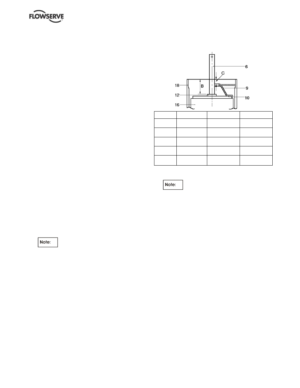
6.9.1 Mechanical seal
a) Slide the seal retaining ring (12) onto the shaft and
set in position to dimension 'B' as shown.
Dimension
Seal type
5 and 8WMV
16WMV
B
Crane type 2
(discontinued)
41 mm
(1.614 in.)
40 mm
(1.574 in.)
B
Angus balanced
(discontinued)
41 mm
(1.614 in.)
42 mm
(0.1654 in.)
B
Crane
type 502
39.5 mm
(1.555 in.)
39 mm
(1.535 in.)
B
Flowserve PAC
type P250
39.5 mm
(1.555 in.)
39 mm
(1.535 in.)
C
Any
13.6 - 14.1 mm
(0.535 - 0.555 in.)
12.6 - 13.1 mm
(0.496 - 0.516 in.)
NB: tolerance on B setting is +1.0 mm - 0.0 mm
b) Lock in position with socket screw.
c)
Set seal retaining ring with shaft in
bottom position. (For the superseded Angus
balanced seal the same dimension applies down
to the shoulder on the shaft sleeve.)
d) Fit the pre-load cone (9) and such shims (10) as
are necessary to maintain dimension 'C' as
shown. The pre-load cone must be kept firmly
pressed down whilst checking the dimension.
Use shims 1 mm (0.04 in.) and 0.5 mm (0.02 in.)
thick as required.
e) Lift off the pre-load cone and shims, apply soap
or light oil to the shaft and slide on the seal unit,
up to the retaining ring for the crane seal (or to
the shoulder on the sleeve for the Angus seal).
f) Re-fit the preload cone and shims. Fit the seal
seat in the motor stool.
g) Lower the motor stool over the shaft and tie rods
and into the end of the outer casing, aligning the
filling/vent connection as shown on the outline
arrangement drawing or as required.
h) Take care not to damage the seal seat on the
end of the shaft when fitting the motor stool. The
shoulder on the motor stool will not fit all the way
down to the end of the outer casing until the tie
rod nuts are tightened because of the spring
pressure from the pre-load cone.
i)
Tighten the tie rod nuts to the torque listed.