Flowserve BX2001 Durco User Manual
Page 21
DURCO BX2001 USER INSTRUCTIONS ENGLISH 9-13
21
cLEAn up AnD prEpArAtIon
1. Clean and inspect seat components and valve disc, follow-
ing the procedure for seat replacement in Section IV.
2. Remove any gasket material from the seat pocket,
packing box and shaft bore of the valve body. Clean all
surfaces thoroughly. Polish the valve body packing and
stem bores, the disc shaft bore and the shaft using
600 grit or finer emery paper.
3. Carefully inspect all machined bores and surfaces. Small
scratches, scale or minor corrosion can be removed by
polishing using 600 grit or finer emery paper. Under
no circumstances should heavily worn, corroded or
scratched valve bodies, discs or shafts be repaired by
welding or re-machining.
SECTION VII
COMPLETE VALVE REPAIR
DISASSEMBLY
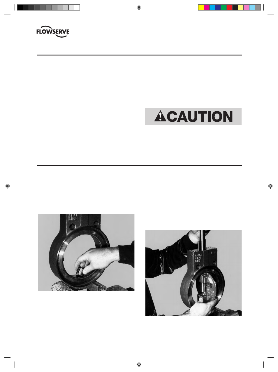
1. Place the valve seat side up on a work table and remove
manual operators.
2. Remove seat package following the procedure for seat
replacement in Section IV.
3. Remove packing bolts or nuts, adjuster and gland.
Remove external disc support hardware or bottom cap.
4. Grind away weld from end of disc pin and drive out pins
using a punch and hammer. Discard pins.
5. Carefully pull or push shaft through the disc and out of the
valve body.
6. Remove packing and bearings from valve body and discard.
vALvE ASSEMBLY — 2" thru 12"
1. Clamp the valve body in a vice and insert the bearing(s)
into the bottom (blind) shaft bore. For PTFE/fiberglass
bearings, insert the bearing stack as shown in Table D.
For severe service, fire sealed and metal bearings, insert
the short bearing into the bottom shaft bore. Note: Severe
service and fire sealed bearings are split. Align the split
towards one side of the valve.
2. Place one disc thrust washer over the bearing and then
place the disc (disc pin slot up toward the top end of the
valve body) into the valve body, aligning the disc and body
shaft bores. Slide the second disc thrust washer into the
gap between the top of the disc and valve body.
3. Insert the top bearing(s) into the top shaft bore of the
valve body. For PTFE/fiberglass bearings, insert the bear-
ing stack as shown in Table D. For severe service, fire
sealed and metal bearings, insert the long bearing into
the top shaft bore. Note: Severe service and fire sealed
bearings are split. Align the split of the top bearing in the
opposite direction of the bottom bearing.
4. Slide the shaft through the top bearing and disc and into
the bottom shaft bore. When fully inserted, the disc pin
slot of the disc and shaft will be aligned.
Do not sandblast the valve body, disc or shaft.
(DVENIM0390-02)-BX2001_update.indd 21
10/10/13 2:08 PM