Flowserve BX2001 Durco User Manual
Page 26
DURCO BX2001 USER INSTRUCTIONS ENGLISH 9-13
26
SECTION VIII
MANUAL GEAR OPERATOR INSTALLATION
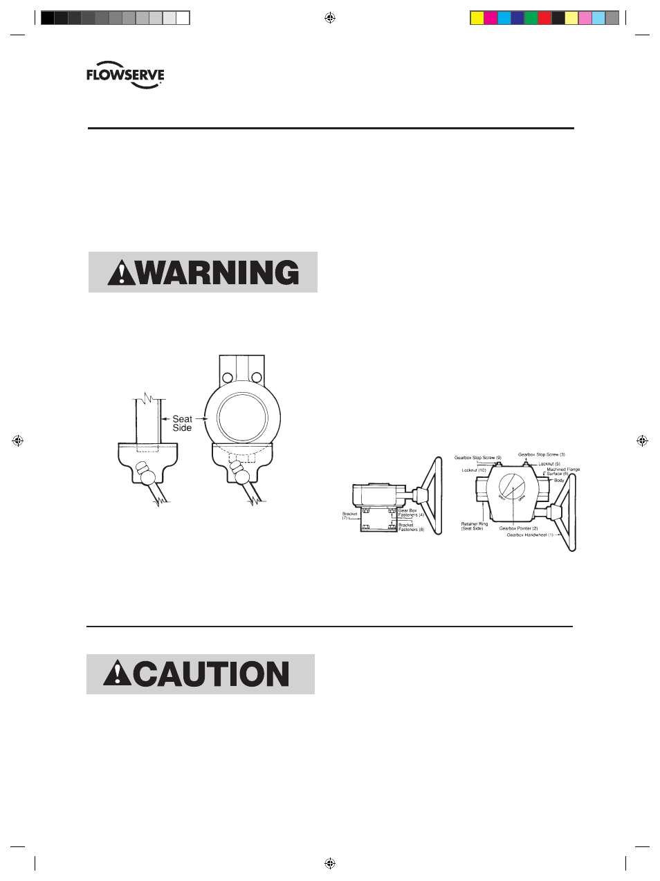
1. Close the valve. The flats on top of the stem should be
parallel with the valve flange face. (Refer to FIGURE
6.) Note: At this time, adjustments should be made to
ensure that the body’s machined flanged surface (6) is
parallel with the disc. To accomplish this, place the valve
body’s machined flange surface (6) on a level plate.
Position a bubble level on the upper side of the shaft flat
and adjust the shaft until completely level.
When placing the valve into the vice, grip the bottom of the
valve only. Do not grip the bottom edge of the retainer ring,
this can damage the retainer ring/gasket sealing surface. Refer
to FigurE 5. Note: Vice should have soft jaws.
FIGURE 5
Recommended method
Alternate method acceptable
but not recommended
2. Place bracket (7) on the valve body as shown in FIGURE 6.
Attach using the brackets fasteners (8), lock washers
and hex nuts, making the fasteners finger-tight.
3. Rotate the gearbox handwheel (1) clockwise until the
gearbox pointer (2) indicates the “shut” position.
4. Place the gearbox on the bracket (7) as shown in
FIGURE 6.
5. Loosen the gearbox stopping screws (3) and (9).
6. Install the gearbox fasteners (4) and lock washers and
tighten. Bracket fasteners (8) must also be tightened.
7. Turn the gearbox closing stop screw (9) clockwise until
it stops, then tighten the locknut (10).
8. Turn the gearbox handwheel (1) counterclockwise to
open the valve until the disc face is perpendicular to the
valve body flange face.
9. Turn the gearbox opening stop screw (3) clockwise until
it stops, then tighten the locknut (5).
10. Cycle the valve from closed to open to closed again
using the gear operator. Recheck to make sure the disc
is centered on the seat by measuring the distance from
the machined surface on the disc to the machine flanged
surface (6) on the body. This should be done at two
points, one above or below the disc over travel stop and
the other 180 degrees from the first. Both measurements
should be equal.
FIGURE 6
(See FIGURE 5 and FIGURE 6 below.)
SECTION IX
CHANGING MANUAL GEAR OPERATOR QUADRANTS
if valve is installed as valve could open when the manual
gear operator is removed.
2. Remove manual gear operator.
3. Remount gear operator 180 degrees from the position
shown in FIGURE 6.
4. Follow Steps 5 through 9 of the Manual Gear Operator
Installation instructions above.
Do not attempt to change the manual gear operator
quadrant while the valve is in service.
1. Close the valve. The flats on top of the stem should be
parallel with the valve flange face. Depressurize system
(DVENIM0390-02)-BX2001_update.indd 26
10/10/13 2:08 PM