Flowserve BX2001 Durco User Manual
Page 7
DURCO BX2001 USER INSTRUCTIONS ENGLISH 9-13
7
SECTION II
INSTALLATION
(Please refer to and follow all recommendations of MSS SP-92)
1. Check valve nameplate before installation to ensure
that the valve’s pressure rating and materials of con-
struction are compatible with the intended service con-
ditions. If lug style, check for end of line service tag.
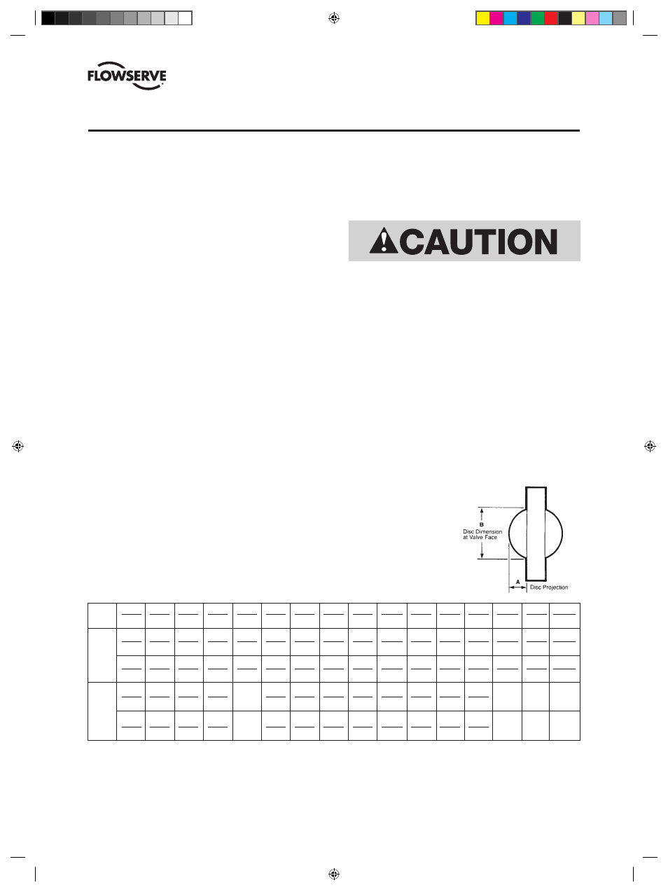
2. Inspect adjoining pipelines and remove any material
that could damage the seat. Check clearance of the
disc projection into the pipeline shown in TABLE B
and FIGURE 1.
3. Check actuator stops before valve is installed and the
line is pressurized. Make certain position indicator
reads “shut” and the disc position is in agreement.
4. The valve must be installed with the disc in the closed
position and centered on the seat.
5. The valve must be properly aligned and centered
between the pipe flanges.
6. The BX2001 is designed for bi-directional shut off
when installed between metallic ANSI B16.5 flanges.
Flow direction should agree with the flow arrow on
the body to assure lower opening torque and longer
service life. With non-metallic flanges, the BX2L4 or
BX2L9 series valve should be used.
7. The use of rubber or other similar “soft” gaskets is
NOT recommended, and should be avoided.
BX2L4 and BX2L9 end of line valves are derated to 150 PSI
maximum when installed without a mating flange supporting
the retainer ring.
8. When standard lug style valves are installed for
end-of-line (dead-end) service, the retainer ring
must be supported by a mating pipe flange. For true
end-of-line service with retainer ring unsupported,
a BX2L4 or BX2L9 series valve must be used.
TABLE B – Disc Projection
in 2 3 4 5 6 8 10 12 14 16 18 20 24 30
36
(mm) (50) (80) (100) (125) (150) (200) (250) (300) (350) (400) (450) (500) (600) (750) (900)
A in
3
/
8
11
/
16
1
1
/
8
1
1
/
2
2
1
/
16
2
5
/
8
3
5
/
8
4
1
/
2
5
5
25
/
32
6
3
/
8
7
3
/
32
8
5
/
16
11 13
41
/
64
(mm) (10) (17) (29) (38) (52) (67) (92) (114) (127) (147) (162) (180) (211) (279)
(346)
B in 1
1
/
4
2
7
/
16
3
5
/
8
4
1
/
2
5
9
/
16
7 9
5
/
16
11
3
/
8
12
45
/
64
14
45
/
64
16
9
/
16
18
15
/
32
22
23
/
32
28
3
/
8
34
3
/
8
(mm) (32) (62) (92) (114) (141) (178) (237) (289) (323) (373) (420) (469) (561) (721) (873)
A in
3
/
8
11
/
16
1
1
/
8
— 2
1
/
16
2
5
/
8
3
5
/
8
4
1
/
2
4
1
/
8
4
3
/
4
5
3
/
8
6
1
/
4
— — —
(mm) (10) (17) (29) (52) (67) (92) (114) (105) (121) (137) (159)
B in 1
1
/
4
2
7
/
16
3
5
/
8
— 5
9
/
16
7 9
5
/
16
10
3
/
4
12
1
/
8
14
1
/
8
15
7
/
8
17
1
/
4
— — —
(mm) (32) (62) (92)
(141) (178) (237) (273) (310) (358) (402) (438)
ASME
Class
150
Size
ASME
Class
300
FIGURE 1
Mating Flange
Clearance Dimensions
9. When BX2L4 or BX2L9 valves are used, check for
compatibility before using API 601 spiral wound
metallic gaskets.
10. Flange fasteners should be tightened and
torqued in a sequential criss-cross pattern as
recommended by the MSS SP-92 standard.
11. For recommended fastener sizes see the tables
at the end of this publication on page 34 and 35.
(DVENIM0390-02)-BX2001_update.indd 7
10/10/13 2:07 PM