4 mounting to maxflo rotary valves, Ounting to, Otary – Flowserve 500+ Series Logix User Manual
Page 17: Alves
User Instructions - Logix® 500+ Series Digital Positioners FCD LGENIM0105-10 11/13
flowserve.com
17
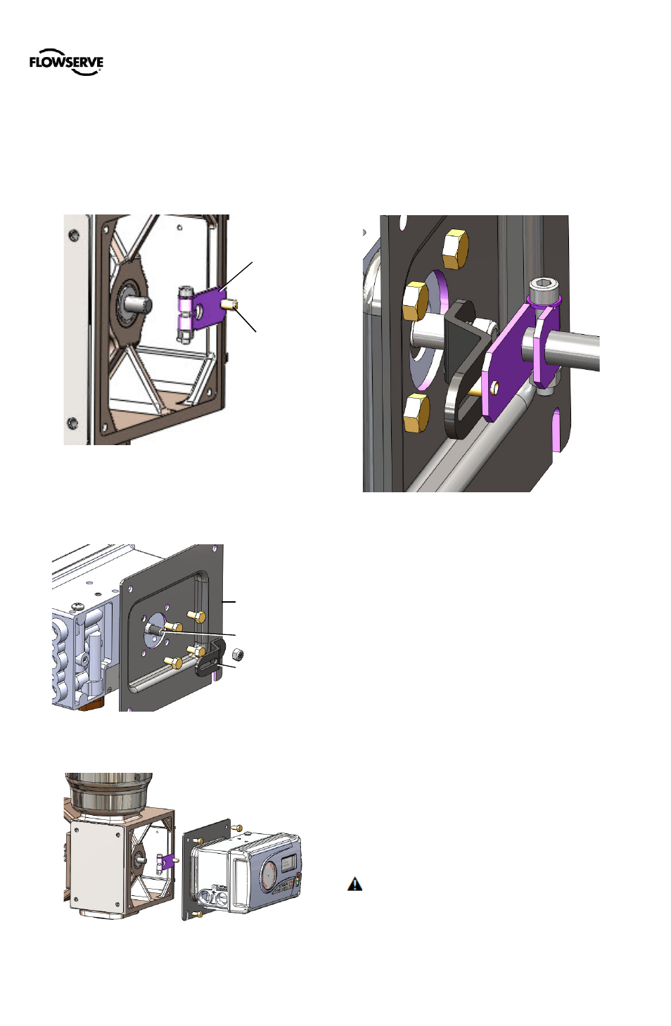
Figure 14: MaxFlo Connection
5.4
Mounting to MaxFlo Rotary Valves
1
Slide the take-off arm onto the shaft. Insert the screw
with star washer through the take-off arm and add the
second star washer and nut. Tighten nut with socket so
arm is lightly snug on the shaft but still able to rotate.
This will be tightened after linkage is correctly oriented.
2
Attach the mounting plate to the positioner using 4
screws.
3
Attach follower arm to positioner feedback shaft.
4
Rotate the follower arm so the take-off pin will slide into
the slot on the follower arm. Adjust the bracket position
as needed noting the engagement of the follower pin
and the take-off arm slot. The pin should extend
approximately 2 mm past the take-off arm. When
properly adjusted, securely tighten the bracketing bolts.
NOTE: The feedback shaft has a clutch mechanism that
allows for over-rotation of the shaft for easy adjustments.
5
Connect regulated air supply to appropriate port in
manifold. See section 6 TUBING.
6
Connect the power to the 4-20 mA terminals. See
section 7 ELECTRICAL CONNECTIONS.
7
Remove main cover and locate DIP switches and
QUICK-CAL/ACCEPT button.
8
Refer to sticker on main board cover and set DIP
switches accordingly. See section 8 STARTUP.
9
Press the QUICK-CAL/ACCEPT button for three to four
seconds or until the positioner begins to move. The
positioner will now perform a stroke calibration.
10
If the calibration was successful the green LED will blink
GGGG or GGGY and the valve will be in control mode.
11
If calibration fails, as indicated by a RGGY blink code,
retry the calibration. If it still fails, the feedback values
were exceeded and the arm must be adjusted away
from the positioner’s limits. Rotate the feedback shaft
so that the full free travel of the feedback shaft is in the
range of the actuator movement. Optionally, continue
to attempt the calibration. Each calibration attempt
adjusts the acceptable limits and it should pass
eventually.
CAUTION: Remember to remove the air supply before
re-adjusting take-off arm.
Figure 11: MaxFlo Take-Off Arm
Take-Off Arm
Take-Off Pin
Figure 13: MaxFlo Follower Arm
Mounting Plate
Follower Arm
Feedback Shaft
Figure 12: MaxFlo Assembly