17 maintenance and repair, 1 scheduled maintenance, 2 required tools and equipment – Flowserve 500+ Series Logix User Manual
Page 45: 3 torque specification for screws, 4 installing a limit switch, Maintenance and repair, Cheduled, Aintenance, Equired, Ools and
User Instructions - Logix® 500+ Series Digital Positioners FCD LGENIM0105-10 11/13
flowserve.com
45
17 MAINTENANCE AND REPAIR
The kits listed in section 20.2 Spare Parts Kits can be
replaced by a technician trained in positioner function and
handling of static sensitive devices.
CAUTION: Depressurize the positioner before servicing.
CAUTION: Use eye protection.
CAUTION: When touching the circuit boards, observe
precautions for handling electrostatically sensitive devices.
17.1 Scheduled Maintenance
The supply gas filter(s) should be scheduled for regular
maintenance as required to maintain supply gas quality. If
contamination is found in the filter, the inside of the positioner
should be visually inspected for contamination. If
contamination is found in the positioner, the positioner should
be replaced.
17.2 Required Tools and Equipment
The Logix 500+ digital positioner has modular components
that can be replaced using these tools:
Figure 40: Tools for Positioner Maintenance
The spool, block and manifold of the double acting relay can
be cleaned using acetone, a soft cotton cloth and cotton
swabs.
17.3 Torque Specification for Screws
Table 24: Torque Specification for Screws
Outer Cover (4 Screws)
1.7 N-m (15 in-lb)
Limit Switch (3 Screws)
0.56 N-m (5 in-lb)
Limit Switch Vane (2 Screws)
0.34 N-m (3 in-lb)
Inner Cover (6 Screws)
0.34 N-m (3 in-lb)
LCD (4 Screws)
0.34 N-m (3 in-lb)
Main Board (2 Screws)
0.34 N-m (3 in-lb)
Pressure Board ( 6 Screws)
0.68 N-m (6 in-lb)
Double Acting Relay Block ( 2 Screws)
0.56 N-m (5 in-lb)
Double Acting Relay manifold (2 Screws) 0.56 N-m (5 in-lb)
Single Acting Relay (2 Screws)
0.56 N-m (5 in-lb)
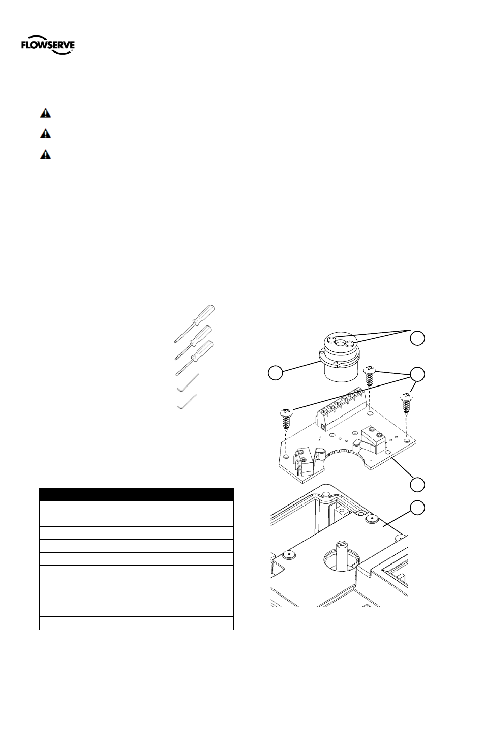
17.4 Installing a Limit Switch
The Logix 500+ digital positioner can be equipped with an
additional limit switch unit. Part of the switching unit attaches
to the feedback shaft. The sensors attach to the inner cover.
Connections to the limit switch are independent of other
connections to the positioner.
For electrical connection diagrams, see Table 14: Limit
Switch Connections. For electrical specifications, see Table
7: Limit Switch Specifications.
DANGER: For units installed in hazardous areas special
installation cautions and procedures are required. The
installation of hazardous location electrical equipment must
comply with the procedures contained in the certificates of
conformance. Country specific regulations may apply.
Electrical safety is determined only by the power supply
device. (Positioner operation with limited voltage only).
Installation
1
Remove the outer cover.
2
Place the limit switch board (1) onto the Inner cover (2)
and secure it with 3 mounting screws (3).
3
Install vane assembly (4) and secure with 2 screws (5).
Adjusting Switches
1
Loosen the two screws on the vane (5).
2
Stroke the valve to the first switching position.
3
Set the switching point of the limit switch by adjusting
the lower vane for the lower switch (LS2).
4
Stroke the valve to the second switching position (LS1).
5
Set the switching point of the limit switch by adjusting
the vane for the upper switch.
6
Tighten the two screws on the vane (5).
7
Attach wires to terminals. See section 7.4 Limit
Switches.
8
Check the two switching points and repeat the
adjustment steps 1 to 6, if necessary.
9
Replace the outer cover.
Figure 41: Limit Switch
2
1
4
5
3
Philips Screwdriver #2
________
Philips Screwdriver #1
________
Slot Screwdriver (
≤ 3.5mm) ________
2.5 mm Hex Key
________
2.0 mm Hex Key
________