11 hart communication, 1 valvesight dtm, 2 hart 375/475 handheld communicator – Flowserve 500+ Series Logix User Manual
Page 39: 3 changing hart versions, 4 burst mode, Hart communication, Alve, Ight, Hart, Andheld
User Instructions - Logix® 500+ Series Digital Positioners FCD LGENIM0105-10 11/13
flowserve.com
39
11 HART COMMUNICATION
The Logix 520MD+ series positioners use the HART
communication protocol specified by the HART
Communication Foundation.
11.1 ValveSight DTM
Flowserve Corporation has produced a custom Device Type
Manager (DTM) for the Logix 520MD+ digital positioners to
support the ValveSight diagnostics platform.
The DTM contains a high level “Dashboard” view of the
system health and status information. It also contains
comprehensive user-friendly interfaces for control and
reporting of alarms, of-line and on-line diagnostic tests,
calibrations and system configurations.
The ValveSight DTM is available from a Flowserve
representative or from www.valvesight.com.
Figure 35: ValveSight DTM Dashboard
11.2 HART 375/475 Handheld
Communicator
The Logix 520MD+ digital positioner supports and is
supported by the HART 375/475 Handheld Communicator.
The Device Description (DD) files can be obtained from the
HART Communication Foundation or from your Flowserve
representative.
11.3 Changing HART Versions
The Logix 520MD+ positioner comes standard with the
HART 6 communication protocol. Follow this procedure to
change to HART 5 or 7.
1
Remove the outer cover.
2
Remove the inner cover by removing the 6 inner cover
retaining screws.
CAUTION:
Observe precautions for handling
electrostatically sensitive devices.
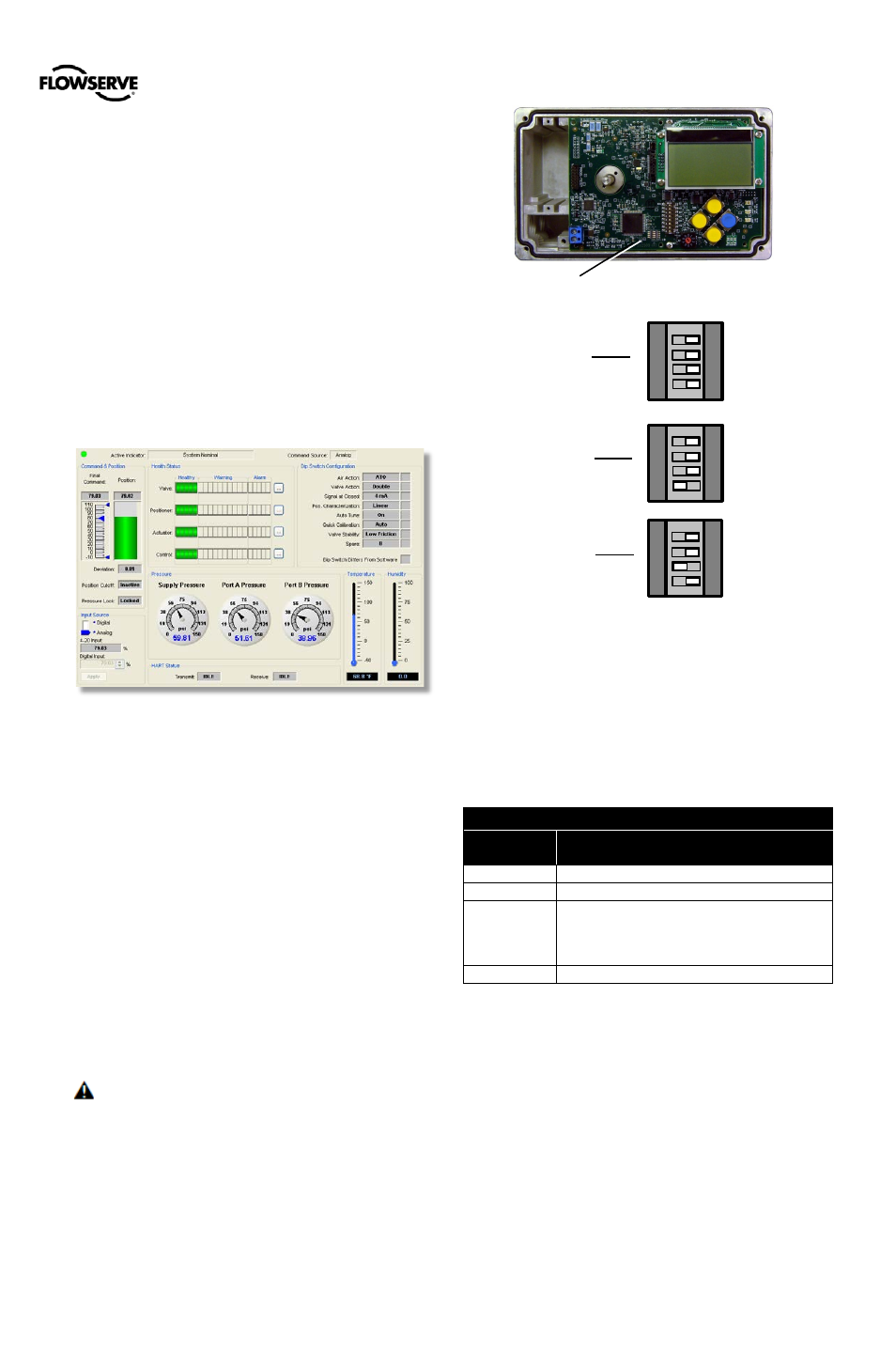
3
With a clean, non-conductive instrument, change the
position of DIP switch according to Figure 36: HART
DIP Switch. After changing the DIP switch, the
positioner will immediately recognize the new HART
communication protocol.
4
Replace the covers.
Figure 36: HART DIP Switch
11.4 Burst Mode
Burst Mode is available with a handheld device. In the
handheld, select the Burst Mode feature under the
Configuration Menu. Variables that are transmitted in burst
mode are shown in the table below.
Table 20: Default HART Parameters for Burst Mode
HART
Variable
Data Description
Primary
4-20 Command (%)
Secondary
Final Command (%)
Tertiary
Purchased with Standard Diagnostics:
Temperature (C)
Purchased with Advanced or Pro Diagnostics:
Supply Pressure (bar)
Quaternary
Valve Position (%)
NOTE: These variable assignments are reestablished
during a factory reset. A field upgrade will not change the
tertiary variable.
NOTE: The DTM will not function while the positioner is in
Burst Mode.
HART DIP Switch
HART 6
(default)
HART 7
1 2
3 4
1 2
3 4
HART 5
1 2
3 4