Reassembly instructions, Cont.), Edward valves – Flowserve V-378 R1 Edward Equiwedge Gate Valve User Manual
Page 22: Table 5—bearing retainer preload torque, Table 5a, Table 6—bearing retainer final torque, Table 6a
22
Flow Control Division
Edward Valves
Reassembly Instructions
(cont.)
j. Install the bearing retainer flange on
the yoke (make certain that the mating
surfaces are clean), align the position
marks and align the holes in the bear-
ing retainer flange with the holes in
the yoke. Install 3 or 4 cap screws at
900 intervals. Use a depth micrometer
to level the bearing retainer flange
and take readings to ensure that the
flange remains level while the torque
is increased in small increments.
Rotate the yoke bushing after each
increase in torque. Apply a preload
torque indicated on Table 5 to the cap
screws, use a depth micrometer to
take measurements and compare the
measurements with those taken in step
(a) above. If the measurements are the
same as those recorded in step “a”,
then the flange has bottomed on the
yoke. If the measurements are greater
than “a” measurements, then the
flange has not bottomed and the bear-
ing preload procedure should be
repeated. Install the remaining cap
screws and tighten in a star pattern
until the torque indicated in Table 6 is
developed. Be careful to keep the
bearing retainer flange level while
torque is applied to the cap screws.
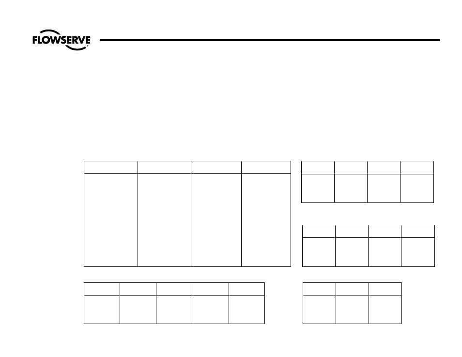
Table 4—Dimensions For Bearing Preload Washer - in inches (mm)
Valve Stem Diameter
Washer OD
Washer ID
Washer Thickness
+.005
(±.13)
+.010
(±.25)
+.001
(±.03)
2.000
(50.80)
5.100
(129.54)
4.56
(115.8)
.187
(4.75)
2.125
(53.98)
5.100
(129.54)
4.56
(115.8)
.187
(4.75)
2.250
(57.15)
5.687
(144.45)
5.15
(130.8)
.187
(4.75)
2.375
(60.32)
6.090
(154.69)
5.38
(136.7)
.187
(4.75)
2.500
(63.50)
7.110
(180.59)
6.40
(162.6)
.187
(4.75)
2.625
(66.68)
7.075
(179.70)
6.36
(161.5)
.187
(4.75)
2.750
(69.85)
6.985
(177.42)
6.30
(160.0)
.187
(4.75)
2.875
(73.02)
8.110
(205.99)
7.34
(185.9)
.187
(4.75)
3.000
(76.20)
8.985
(228.22)
8.12
(206.2)
.187
(4.75)
3.250
(82.55)
9.985
(253.62)
9.00
(228.6)
.187
(4.75)
3.500
(88.90)
11.360
(288.54)
10.25
(260.3)
.187
(4.75)
3.750
(95.25)
12.485
(317.12)
11.25
(285.8)
.187
(4.75)
4.250 (107.95)
12.485
317.12)
11.25
(285.8)
.187
(4.75)
Table 5—Bearing Retainer Preload Torque
Cap Screws
Threads Per
Torque In Ft.
Torque
No. of Cap
Diameter
Inch
Pounds
In NM
Screws
3/4
10
20
27
3 or 4
7/8
9
35
47
3 or 4
1
8
50
68
4
1-1/4
7
135
183
4
Table 5A
Cap Screws
Pitch
Torque
No. of Cap
Diameter
in NM
Screws
16
2
120
3 or 4
20
2.5
240
3 or 4
24
3
400
3 or 4
30
3.5
880
4
Table 6—Bearing Retainer Final Torque
Cap Screws Threads Per Torque in Ft.
Torque
Diameter
Inch
Pounds
in NM
3/4
10
165
224
7/8
9
265
360
1
8
405
550
1-1/4
7
895
1215
Table 6A
Cap Screws
Pitch
Torque
Diameter
in NM
16
2
120
20
2.5
240
24
3
400
30
3.5
880