Introduction and scope, Edward valves, Introduction – Flowserve V-378 R1 Edward Equiwedge Gate Valve User Manual
Page 3: Scope, Gate valve figure numbers described in this manual
3
Flow Control Division
Edward Valves
Introduction and Scope
Introduction
This manual has been prepared to serve as
a guide for maintenance of Edward
Equiwedge gate valves, all of which
feature the pressure seal bonnet joint
construction. Although rigid metallurgical,
non-destructive examination, physical and
visual inspection is standard procedure for
Edward Valves products, it is inevitable
that some valves, after a period of time,
will require repairs. This manual will assist
you in restoring the valve to good working
condition with a minimum of time and
expense.
Scope
Before starting any repairs, it will be
helpful to have some understanding of the
valve’s physical construction. Consequently,
the five basic types of pressure seal con-
struction are discussed and illustrated first.
All Equiwedge gate valves employ one of
these five basic types.
The next major section of this manual
discusses the more common service
problems, and explains the reason for
certain failures. The reason for the problem
should be understood before work is actu-
ally started.
Then, the procedure to be followed in mak-
ing the repair is explained. This section
includes normal valve maintenance as well
as major valve repairs. Field repair equip-
ment available from Edward Valves is
described and illustrated. Valve lubrication
and welding rod recommendations are
also included. These procedures should be
adequate for almost any Equiwedge gate
valve repair or maintenance problem that
may arise.
Following is a section describing the
disassembly procedure for the various
valve components; for example, manual
handwheel, manual geared actuators or
electric actuators, valve yokes, and the five
basic bonnet types. It is very important that
this manual be studied before any
disassembly work is done to avoid need-
less work and loss of time by selecting the
improper procedures.
The last sections include reassembly instruc-
tions and available maintenance equip-
ment and information on the various types
of actuators, both manual and electrical.
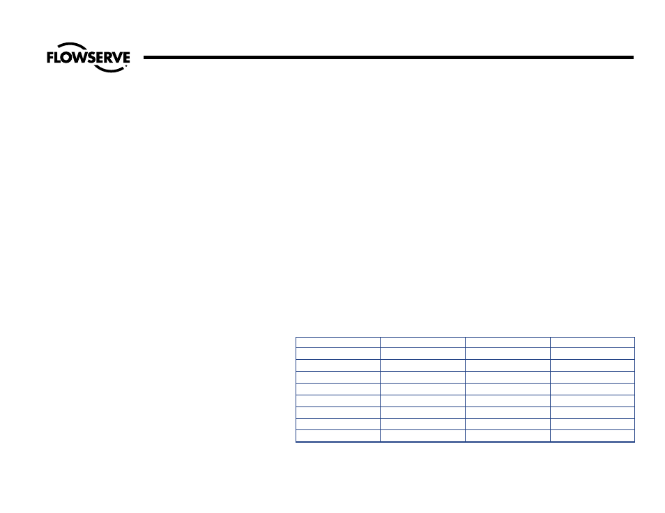
Figure No.
Class
Pressure Seal Type
Size
1611-1611Y
600
I & II
2
1
⁄
2
to 28
1711Y
Special Class 600
I & II
2
1
⁄
2
to 28
1911-1911Y
900
III, IV, & V
2
1
⁄
2
to 28
14311Y
Special Class 900
III, IV, & V
2
1
⁄
2
to 28
11511-11511Y
1500
III, IV, & V
2
1
⁄
2
to 24
12011Y
Special Class 1500
III, IV, & V
2
1
⁄
2
to 24
12511-12511Y
2500
III, IV, & V
2
1
⁄
2
to 24
14411Y
Special Class 2500
III, IV, & V
2
1
⁄
2
to 24
Gate Valve Figure Numbers Described in this Manual