Appendix a – Flowserve V-378 R1 Edward Equiwedge Gate Valve User Manual
Page 28
28
Flow Control Division
Edward Valves
Procedures For Removing Manual
And Electro-mechanical Actuators
From Valve Yokes
Equiwedge pressure seal gate valves are
often equipped with a variety of manual
and/or electro-mechanical actuators. A
number of these are illustrated in this sec-
tion. Basically, there are two types of actu-
ators:
(a) Those which take both torque and
thrust forces.
(b) Those which supply only the torque
to open or close the valve.
In type (a), the actuator is equipped with a
stem nut and thrust bearings that can with-
stand the thrust and torque loads imposed.
THIS TYPE SHOULD NOT BE REMOVED
WITH PRESSURE IN THE VALVE.
In type (b),the actuator is connected to the
valve yoke bushing by a key or spline, or
by other means, and delivers only the
torque load.
The most common is type (a) because of
the non-revolving, rising stem. This type is
used in both manual and electro-mechani-
cal actuators.
TYPE (a) TORQUE AND THRUST
ACTUATOR DISASSEMBLY
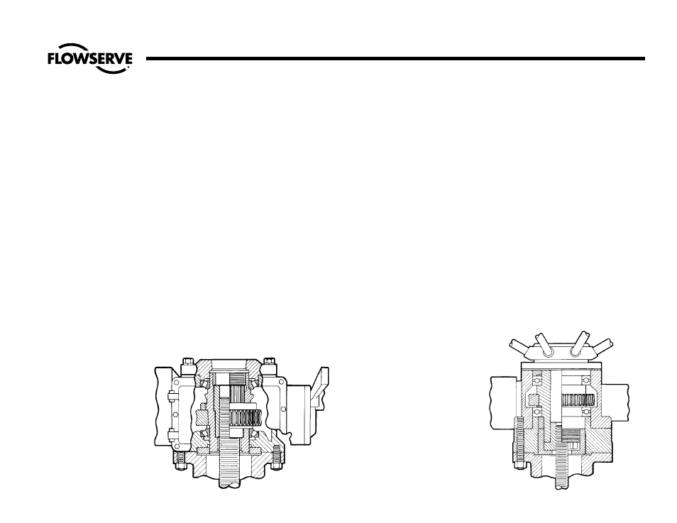
Limitorque Actuator Illustration No. 18
Rotork Units Illustration No. 19
Torkmatic units (Manual)
Illustration No. 20, pg. 29
Auma units Illustration No. 21, pg. 29
Follow these guidelines:
1. Position the valve gate just off the
seat.
2. Disconnect the electrical wiring to the
actuator.
3. Make sure the packing gland nuts
are tight.
4. Position a chain hoist of suitable
capacity to support the actuator so
that the handwheel can be rotated.
The pull point must be directly in line
with the stem.
5. Remove all nuts or cap screws from
the under side of the yoke flange.
6. Turn the actuator handwheel to close
the valve. This will cause the actuator
to rise and unthread the stem nut
from the stem. As this takes place, the
weight of the actuator should be
taken by the hoist to prevent damage
to the stem threads.
7. When the stem threads are disen-
gaged, lift the actuator clear of the
stem and place it down on a clean
area for further disassembly, if
required. If there is additional work
to do on the valve, refer to the prop-
er valve type and proceed to disas-
semble the valve.
Appendix A
Limitorque Actuator
Rotork Actuator
Illustration No. 18
Illustration No. 19