Troubleshooting – Flowserve SMB Series Electric Actuators User Manual
Page 103
103
SMB Series/SB Series Installation and Maintenance FCD LMENIM1401-04-AQ – 01/15
flowserve.com
9
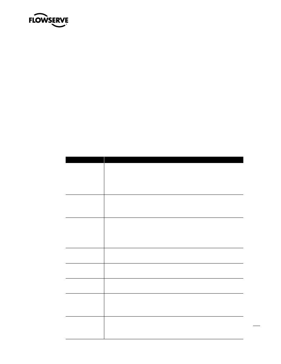
Troubleshooting
Symptom
Corrective Action
Geared limit switch fails
to stop valve travel.
a. Verify that the control wiring and motor reversing contactor wiring are correct.
b. Check the geared limit switch setting. See Section 4.4, Setting Limit Switch.
c. Remove the limit switch gear box cover and inspect for damaged or broken gear teeth. See
Sections 7 and 8, SMB Disassembly and Reassembly and SB Disassembly and Reassembly.
Unable to motor-operate
the actuator.
a. Check the motor power and motor control circuits for supply and continuity.
b. Verify that the supply voltage is in accordance with motor and controller nameplate rating. If
OK, check the motor amperage load.
c. If a stalled motor is indicated, turn the power OFF and operate the actuator by handwheel.
Excessive handwheel
effort.
a. Inspect the valve stem for proper lubrication or damage.
b. Check the valve packing gland. It may be too tight. Loosen the valve packing gland.
c. Inspect the valve for proper lubrication.
d. Check the stem nut for tightness on the valve stem. Loosen the stem nut on the valve stem.
e. Inspect the valve for faulty or damaged parts.
Reversing starter
contacts fail to close.
Check the line circuit breaker or fuses in the disconnect switch (if installed) for possible
interruption of incoming line voltage. The holding coil may be open-circuited and, if so, should
be replaced.
Pushbutton contacts not
making proper contact
when depressed.
Adjust the contacts for correct movement and proper contact pressure.
Overload relays are
open.
Reset the relays. Continued tripping of the overload relays usually indicates trouble with the
motor or improper sizing of the overload heater. See the electric motor nameplate for full load
current.
Reversing starter
contact movement is
restricted.
a. Check for worn or damaged mechanical parts.
b. Clean, adjust, and align all parts for free movement.
c. Replace any defective parts. When replacing the contacts, the complete set of moving and
stationary contacts should be changed along with springs to assure proper contact pressure.
Pushbutton contacts
stick.
a. Trace out the connection of pushbutton contacts with thewiring diagram for actual
installation.
b. Adjust the contacts for free movement and normal contact pressure.
c. Check the wiring for “sneak in” or grounded circuits and defective insulation.
For more information please contact [email protected]