Flowserve SMB Series Electric Actuators User Manual
Page 29
29
SMB Series/SB Series Installation and Maintenance FCD LMENIM1401-04-AQ – 01/15
flowserve.com
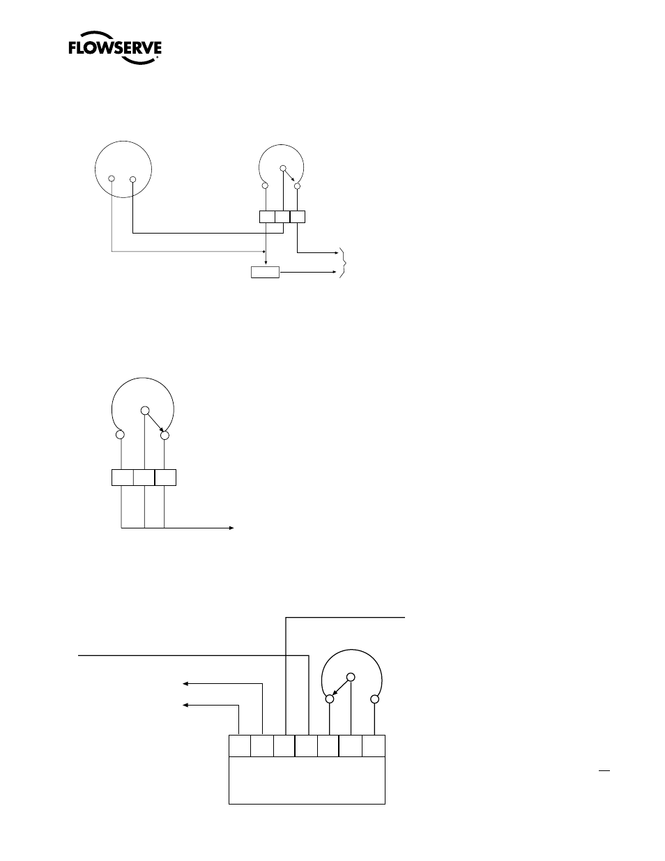
Figure 4.7 – Typical Connection for a 50-ohm Potentiometer
Figure 4.8 – Typical Connection for a 1000-ohm Potentiometer
Figure 4.9 – Typical Connection for R/I Signal Converter (Older Version)
RES
Remote position indicator
0-10 volts full scale deflection
25 Watt, 50 OHM Potentiometer type
variable resistor mounted in SMB/SB housing
Voltmeter
type
Control voltage range
110 volts to 480 volts
175 Watt, 2500 ohm Adjustable resistor
to be located adjacent to remote position indicator
for voltage adjustment
P3
P2
P1
Potentiometer 1000 ohm 2 Watt
in limit switch housing
To customer’s equipment
P1 P2
(CCW)
P3
(CW)
Potentiometer slider rotates
toward counter clockwise (CCW)
terminal as valve opens
4-20 mA
Output Signal
(–) (+)
R to I Signal Converter
PC Board
Connection
91 90 CL2 CL1 P1 P2
P3
91
(–)
90
(+)
C
L2
C
L1
P1
POT
1000 ohm
P3
P2