2 layout – Foxconn R10-H1 User Manual
Page 11
Advertising
4
1
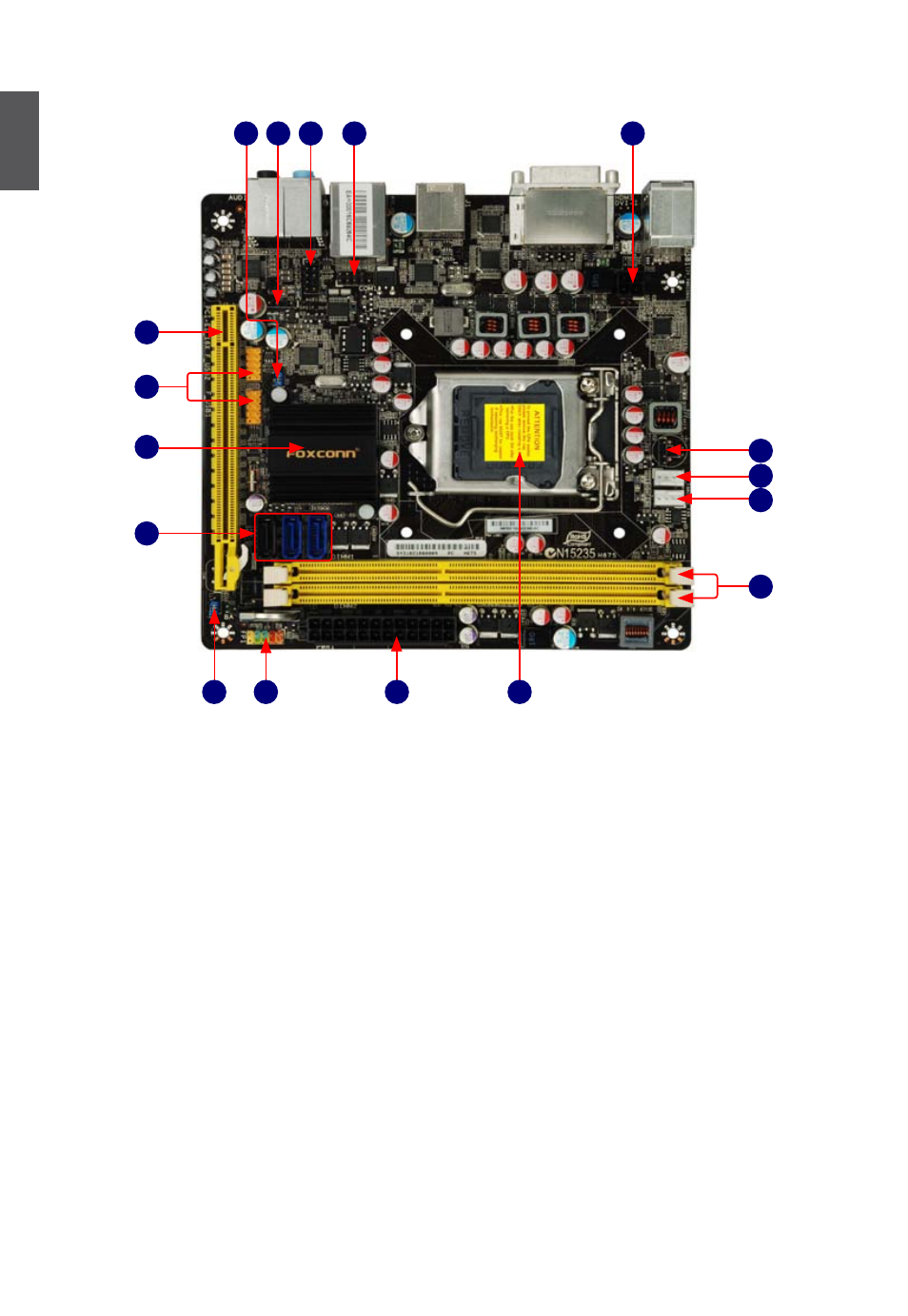
1-2 layout
Note : The above motherboard layout is for reference only, please refer to the physical
motherboard for detail.
1. 4-pin ATX 12V Power Connector
2. COM1 Connector
3. Front Audio Connector
4. S/PDIF_OUT Connector
5. MFG Jumper
6. PCI Express x16 Slot
7. Front USB Connectors
8. PCH: Intel® H67
9. SATA Connectors
10. Clear CMOS Jumper
11. Front Panel Connector
12. 24-pin ATX Power Connector
13. LGA 1155 CPU Socket
14. DDR3 DIMM Slots
15. CPU Fan Header
16. System Fan Header
17. Speaker Connector
2
4
1
8
6
11
12
13
15
17
3
5
9
10
14
16
7
Advertising