GAI-Tronics 10959-101 Wall-Mount Audio Messenger Interface (AMI) User Manual
Page 14
Pub. 42004-398E
M
ODEL
10959-10
X
W
ALL
-M
OUNT
A
UDIO
M
ESSENGER
I
NTERFACE
P
AGE
12 of 31
f:\standard ioms - current release\42004 instr. manuals\42004-398e.doc
10/09
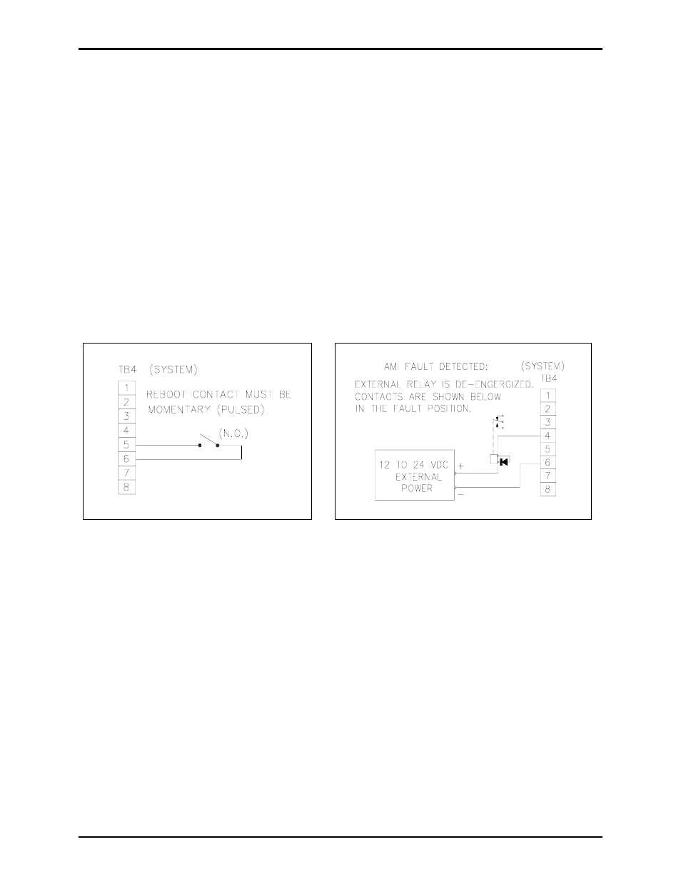
TB4 - Reboot and Fault Output
Reboot
The reboot terminals (TB4-5 and TB4-6) override and abort any activity in progress. To control the
reboot function, a user-supplied, remote, momentary, normally open (N.O.) switch contact closure must
be connected between TB4-5 and TB4-6 (or other GND return). Refer to the TB4 terminal block
assignment chart and Figure 5 below.
Fault Output
If the AMI processor is operating, the fault output is on (TB4-4 active low) and can be used to energize
external relays or indicating devices. If a fault is detected that prevents the AMI processor from
functioning, or if the CompactFlash
®
card is removed, or if communication is lost with one of the
auxiliary boards, the output is turned off (pulled high). Refer to Figure 6 and TB4 (SYSTEM) terminal
block assignments below, which provide the following external control functions:
N
OTE
: For the inputs to operate reliably, the cable loop resistance connecting any relay/switch contact
closures cannot exceed 200 ohms. For example, using No. 24 AWG cable, the maximum cable length for
connection of the relay/switch contact closures cannot exceed 1,500 feet.
Figure 5. Typical reboot switch wiring
Figure 6. Typical fault configuration shown using
external relay with dry contact