GAI-Tronics 10959-101 Wall-Mount Audio Messenger Interface (AMI) User Manual
Page 17
Pub. 42004-398E
M
ODEL
10959-10
X
W
ALL
-M
OUNT
A
UDIO
M
ESSENGER
I
NTERFACE
P
AGE
15 of 31
f:\standard ioms - current release\42004 instr. manuals\42004-398e.doc
10/09
N
OTES
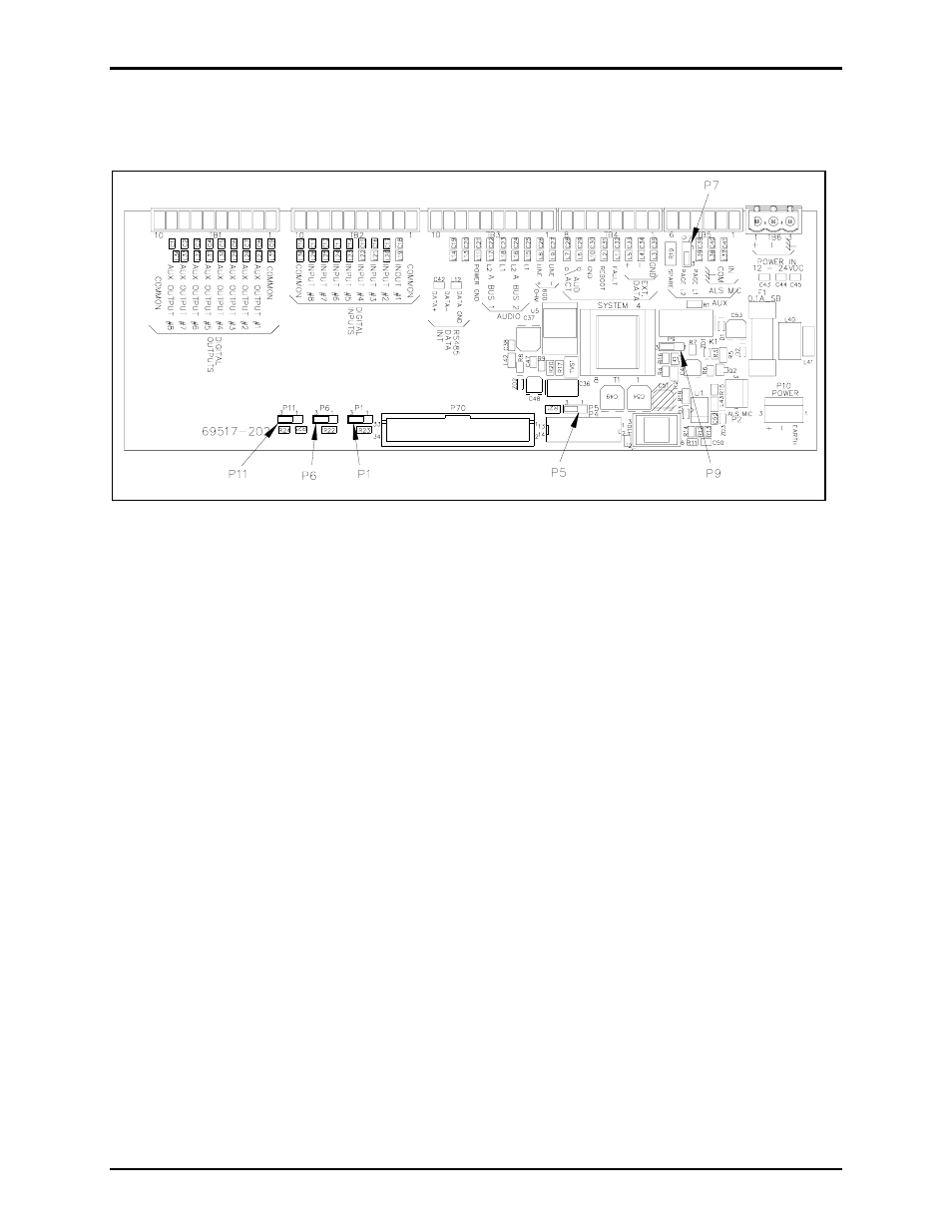
: P1, P5, P6, and P11 are for use with ADVANCE systems.
P9: Use the 33-ohm termination resistor only if there is not a termination resistor already on the page
line.
Figure 8. Jumper Locations on Termination PCBA
Telephone Line Connection
For AMI units equipped with a Telephone Interface board 69501-xxx (Models 10959-103 and 10959-
104), connections are made to a standard PBX analog station port, or directly to a central office (CO)
telephone line.
For Models 10959-103 and 109-104, the incoming telephone line must be connected to the tip (E1) and
ring (E2) of the Registered Line Module (SPRLM-3). A telephone cord with a modular RJ-11 plug is
provided.
N
OTE
: The telephone interface requires a minimum loop current of 25 mA.