Printer interface – GAI-Tronics CommandPLUS Series Desktop Console Installation and Service Manual User Manual
Page 40
Features and Options CommandPLUS Series Desktop Console Installation and Service Manual
12/10 36
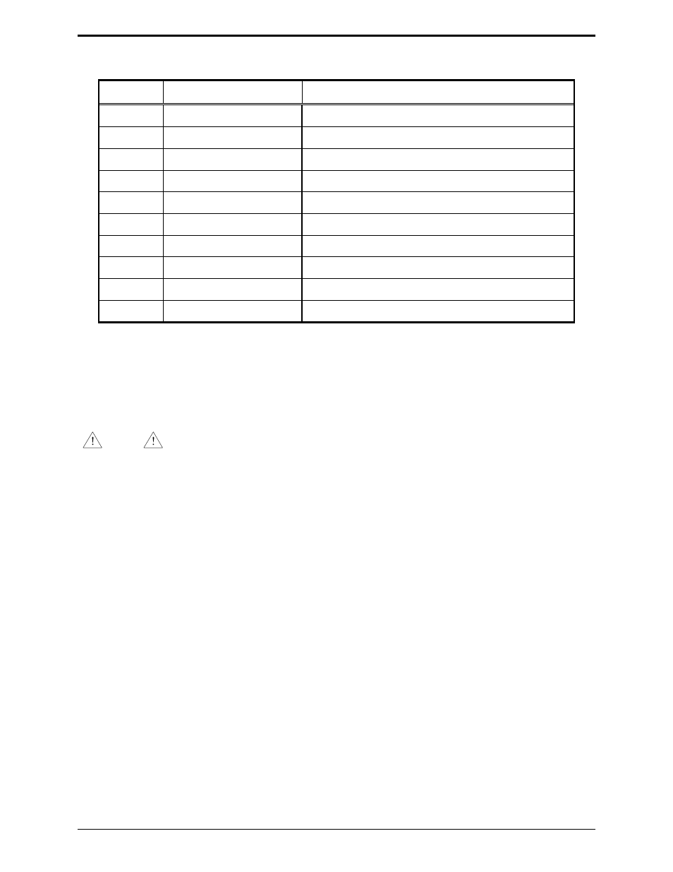
Table 12. Accessory I/O – DB15 Male Connector
Pin No.
Pin Function
Asserted State
1
Encode control IN 4
Indicates that receive audio on CIU 4 is coded
2
Encode control IN 3
Indicates that receive audio on CIU 3 is coded
3
Encode control OUT 3
Instructs CIU 3 to transmit in the clear mode
4
Encode control OUT 4
Instructs CIU 4 to transmit in the clear mode
5
General Purpose I/O 2
6
General Purpose I/O 1
7
Encode control OUT 1
Instructs CIU 1 to transmit in the clear mode
8
Encode control OUT 2
Instructs CIU 2 to transmit in the clear mode
12
Encode control IN 1
Indicates that receive audio on CIU 1 is coded
15
Encode control IN 2
Indicates that receive audio on CIU 2 is coded
Printer Interface
The Printer feature, when enabled through the CARD Suite Software, allows a printed log of receive
DTMF decode and signaling information to be captured.
NOTE
The printer feature requires the use of a serial printer. A parallel printer output
is not available.
Installation
1. Use the CARD Suite Software application to configure the console:
a) The Printer Installed selection (Console Parameters tab) must be enabled.
b) Select the desired Printer Incoming Messages and Printer Outgoing Messages on the Digital
Signaling Console Parameters tab.
2. After console programming has been completed, disconnect the programming cable from the RS232
port.
3. Attach a customer-provided 25-pin serial interface (DB25) from the printer interface cable to the
printer and the 15-pin interface to the RS232 & I/O connector. Secure the plug screws on each
interface. Refer to the printer’s instruction manual for additional information concerning printer use.