Operation and wiring, Transformer assembly – Greenheck Vari-Green Motor (IOM 473681) User Manual
Page 2
2
Vari-Green Motor and Controls
Operation and Wiring
-
Potentiometer Dial Only
These motors feature a potentiometer dial on the motor
for speed adjustment. A small screwdriver can be used
to make the speed adjustment. To increase the speed,
rotate the dial clockwise. To decrease the speed, rotate
the dial counter clockwise.
The motor is pre-wired at the factory and cannot be
changed inside the motor. Connect single-phase power
at the voltage listed on the nameplate.
These motors cannot be converted to receive a remote
control signal – a different motor is needed. Please
consult the factory.
Features, Operation,
Wiring and Troubleshooting
Features
Soft start – All motors
feature soft-start
technology which
eliminates inrush
current at start-
up. The motors will
reliably start at any
speed setting.
Overload protection – If the motor becomes
overloaded, it will automatically reduce its speed until it
is no longer overloaded. This means that the motor will
never operate in the “service factor” which is possible
with many AC motors.
Locked rotor protection – If the motor ever encounters
a locked-rotor scenario, the motor will automatically
shut itself down. It will try to restart up to 3 times, and if
after the 3rd time the motor will still not rotate, the motor
will not attempt to start again until power is cycled.
Thermal protection – The motors have a one-shot fuse
thermal protector. This is meant to protect the motor
from a severe temperature rise. Additionally, the motors
have on-board temperature sensors which will reduce
the speed of the motor should it become too hot. The
fuse is used as a last resort to prevent a fire.
RPM measurement – The motors have a small shaft
extension on the end of the motor to measure motor
RPM with either a contact or optical tachometer.
Part Numbers Covered in this Section
309025
309026
310107
310306
310307
311352
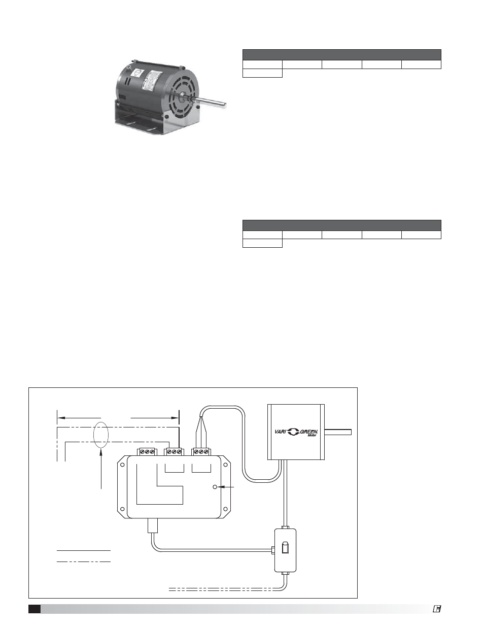
These motors will accept a 0-10 VDC control signal for
speed control. From 0-1.9V, the motor will be off, and
will operate in the 2-10V range. 24 VAC/DC power is
also required for operation. The motor will consume
0.7VA at 24 VAC or 25mA at 24 VDC. A factory mounted
transformer is available to supply this voltage. See Fig. 1
The motor is pre-wired at the factory and cannot be
changed inside the motor. Connect single-phase power
at the voltage listed on the nameplate, along with the
0-10 VDC and 24V signal for speed control.
NOTE: The motor will not operate without the proper
control voltages.
Operation and Wiring
-
0-10V Input Only
Part Numbers Covered in this Section
309028
309029
310108
310475
310476
311353
100 ft. or less
White
Black
Red
COM
24V
0-10V
COM
24V
0-10V
N.C.
COM.
N.O.
Control
Motor
TRANSFORMER
Trip Point = 1.85VDC
Contact Rating:
10A @ 24-240VAC
5A @ 30VDC
Auxiliary
Contact
TO REMOTE DEVICE
PROVICED BY
OTHERS
Low voltage, route away
from high voltage lines
and/or use shielded cable
Factory Wiring
Field Wiring
115/230 VAC input
to match motor name plate
Green indiator light
—Power present
2 x 4
Junction
Box
Transformer Assembly
Fig. 1
0-10 VDC External connection with factory mounted transformer
®