Motor rotation, Troubleshooting, Motor does not operate – Greenheck Vari-Green Motor (IOM 473681) User Manual
Page 5
5
Vari-Green Motor and Controls
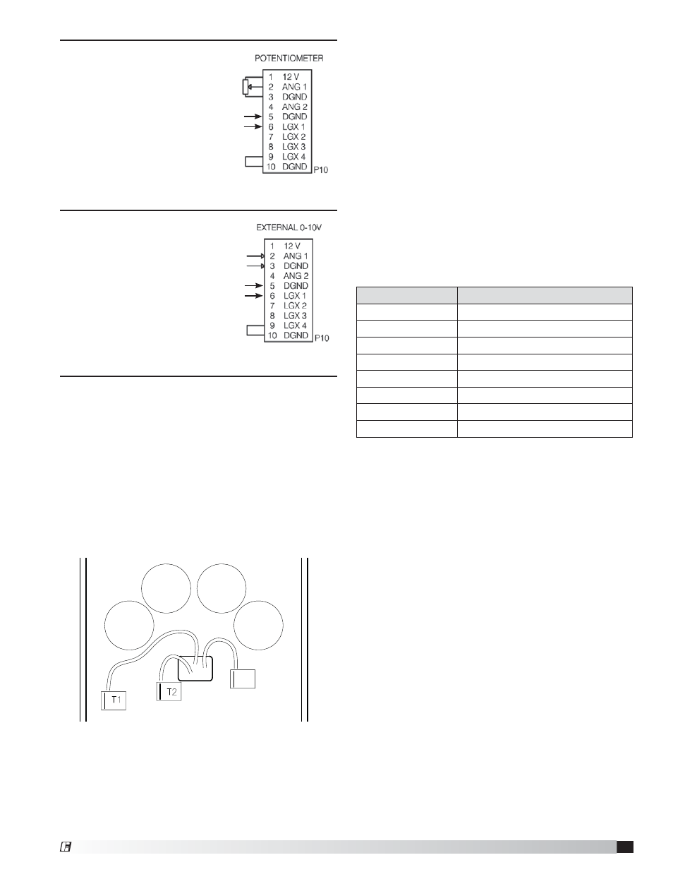
Dial on motor - the dial
is factory-wired into the
low voltage terminal block
inside the control box.
The wires are connected
as shown.
0-10 VDC Signal - a two-wire
pigtail is factory-wired into the
low voltage terminal block.
The wires are connected
as shown.
If the motor needs to be tested before the 0-10 VDC
signal is available, a jumper can be placed between
terminals 1 and 2. This will force the motor to run at
full speed.
Motor Rotation
To reverse the rotation of the motor, swap any two of
the red, black and blue wires connecting the control
board to the motor at terminals T1, T2 and T3. Note
that motor warranty is void if motor is rotating in the
wrong direction. See fan instruction manual for correct
rotation direction.
Troubleshooting
These motors have a diagnostic red LED on the circuit
board inside the control box, or on the exterior of the
control box, that will be solid (not flashing) when power
is applied to the motor and the motor is operating
normally. The LED may be solid even if the motor is not
spinning, such as when power is applied but the motor
may be commanded to be off with a 0-1.9V VDC signal.
1. If external LED is not present, to view the status of
the LED the control box cover must be removed
while power is applied to the motor. If the control
box cover is removed while power is applied,
extreme care must be taken not to touch any of the
components inside the box.
a. If a fault occurs, the LED will blink a specific
number of times to identify the fault that has
occurred. The fault indications are as follows:
3. When the LED is blinking, it will consecutively blink
from 2 to 9 times, followed by a pause, and repeat
the blink sequence. It is best to count the number
of flashes 2 or 3 times to ensure accuracy.
4. Under most fault conditions the motor will
automatically restart. If a motor overload fault occurs
more then 10 times in one hour, the motor will shut
down and require a power cycle to reset.
5. If the fault persists, consult the factory.
Motor does not operate
1. Verify the motor is wired for the correct voltage.
2. Verify that the dial on the motor is properly
connected to the control board - or - verify that
the 0-10 VDC wires are properly connected to the
control board.
3. Verify that the Status LED is solid red.
4. Verify that a jumper is in place between terminals
9 and 10. The motor will not run without this jumper
in place.
5. Verify that the two yellow wires coming from the
motor are in place on terminals 5 and 6.
Dial on motor connection inside control box
0-10 VDC Signal connection inside control box
Rotation selection wires inside control box
T3
Number of Blinks
Indicated Fault
2
Hardware Fault
3
Overvoltage
4
Undervoltage
5
Communication Error
6
Sync Loss
7
Spin Fault
8
Motor overload
9
Motor Over Temperature
RED
WHITE
BLACK
YELLOW
YELLOW
RED
WHITE
YELLOW
YELLOW
®