Greenheck Vari-Green Motor (IOM 473681) User Manual
Page 4
4
Vari-Green Motor and Controls
Wiring
1. All high and low voltage wiring connections are made
inside the motor control box at the factory. Normally,
there is no reason to enter the control box of the
motor. If there is a need to enter the control box,
disconnect power and wait at least five minutes to
allow the capacitors to discharge.
2. The motors are factory wired for the ordered voltage.
If the factory wired voltage does not match the
desired voltage, the voltage can be changed, with
exception of the 2HP motor (310420), which is
208-240V only.
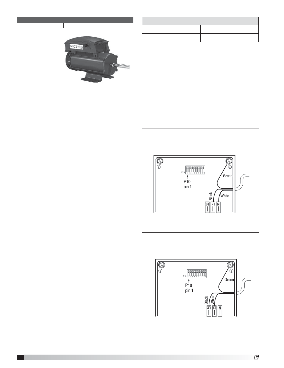
115V: Connect 115 VAC to L1, connect Neutral to N.
The L2 terminal remains empty. Connect ground to
grounding stud.
208-240V - Connect Line voltage to L1 and L2. The
N terminal remains empty. Connect the ground to the
grounding stud.
Part Numbers Covered in this Section
310420
311156
Features
Speed control -
These motors can
be controlled by
either a dial on the
motor or a 0-10 VDC
signal for remote control.
Soft start – All motors feature soft-start technology
which eliminates inrush current at start-up. The motors
will reliably start at any speed setting. There will be up
to a 30 second delay between the application of power
and the motor starting. The motor will "rock" back and
forth upon startup as part of its normal operation.
Overload protection – If the motor becomes
overloaded, it will automatically shut itself down. The
maximum programed motor speeds have been selected
to prevent this from happening in normal operation.
Locked rotor protection – If the motor encounters a
locked-rotor scenario, it will automatically shut itself
down. It will try to restart up to 3 times, and if after the
3rd time the motor will still not rotate, the motor will not
attempt to start again until power is cycled.
Thermal protection – The motors have an automatic
reset thermal protector. This is meant to protect the
motor from a severe temperature rise.
RPM measurement – The motor RPM can be
measured by removing the cooling fan cover and using
a contact or optical tachometer. Be sure to replace the
cooling fan cover when finished.
Reversible rotation – The motor direction has been
pre-set at the factory for the rotation of the fan but can
be reversed if necessary.
Operation and Wiring
These motors can be controlled by either a dial on the
motor or a 0-10 VDC signal for remote control. The
motor will be supplied from the factory with the correct
accessory depending on what was ordered.
Dial on Motor - Turn the dial with your fingers to adjust.
To increase the speed, rotate the dial clockwise. To
decrease the speed, rotate the dial counter clockwise.
Turning the dial full CCW will turn the motor off.
0-10 VDC Signal - From 0-1.9V, the motor will be off,
and will operate in the 2-10V range. This motor does not
require 24V power for operation.
115V Connection inside control box
208-240V Connection inside control box
0-10V Analog input connection
Red
+ 0-10 VDC
White
Ground
®