Troubleshooting - remote dial touch remote, Touch remote, Remote dial/touch remote assembly remote dial – Greenheck Vari-Green Motor (IOM 473681) User Manual
Page 7
7
Vari-Green Motor and Controls
Controls: Operation,
Wiring and Troubleshooting
Remote Dial/Touch Remote and
2-Speed Control
CAUTION
Even though the motor may not be operating,
high voltage power may still be present at the motor.
Make sure to disconnect power to the fan before
servicing.
Troubleshooting -
Remote Dial Touch Remote
Remote Dial does not adjust motor RPM
1. Check voltage to ensure the motor and transformer
are receiving the correct line voltage.
2. Check voltage at the remote dial. 24 VDC should
be present across the 24V and COM terminals.
0-10 VDC should be present across the 0-10V and
COM terminals.
3. Verify all of the connections at the transformer and
make certain that they are secure.
4. Touch remote: Verify that the touch remote is
unlocked.
Terminals
Desired Voltage
24V-COM
24 VDC Nominal
0-10V-COM
0-10 VDC
(varies with dial position)
Other Vari-Green
®
controls, such as the Constant
Pressure and Air Quality families of controls, have their
own manual that ship with the controller. They can also
be found on Greenheck.com. See table on page 9 for
document numbers.
Touch Remote
Follow installation instructions above. After Power is
applied to the system, operate as follows:
1. Touch power button to turn fan on.
2. Touch UP/DOWN arrow to increase/decrease speed.
3. Subsequent touches of the power button will start
the countdown timer of 90, 60, 30 or 10 minutes.
4. LED's will turn off after a periods of inactivity.
5. To lock/unlock buttons, hold the UP and DOWN
arrows for 3 seconds. When locked, the power
button will light up red.
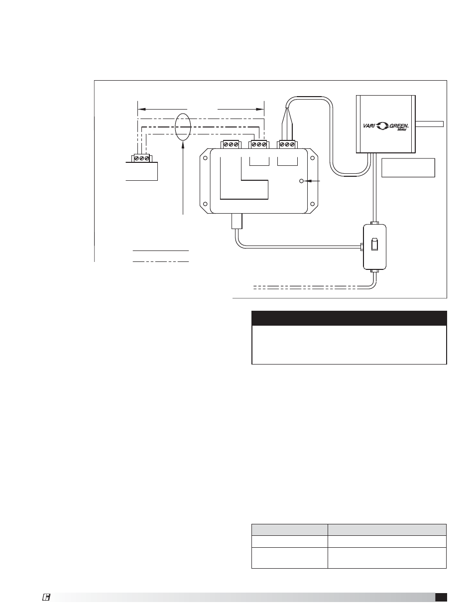
White
Black
*
Red
Low voltage, route away
from high voltage lines
and/or use shielded cable
Factory Wiring
Field Wiring
115/230 VAC input
to match motor name plate
Green indiator light
—Power present
*
NOTE: Black wire not
used on some motors
2 x 4
Junction
Box
Remote Dial/Touch Remote Assembly
Trip Point = 1.85VDC
Contact Rating:
10A @ 24-240VAC
5A @ 30VDC
Auxiliary
Contact
COM
24V
0-10V
COM
24V
0-10V
N.C.
COM.
N.O.
Control
Motor
TRANSFORMER
REMOTE DIAL/
TOUCH REMOTE
0-10V
24V
COM
COM
24V
0-10V
100 ft. or less
Remote Dial/Touch Remote Assembly
Remote Dial
Installation Overview: The remote dial is provided
with the fan, shipped loose for remote installation.
It also includes a factory mounted 24 VDC transformer.
1. Disconnect power to the fan.
2. Identify where the remote dial will be mounted.
3. Mount a standard single-gang 2x4 junction box.
4. Run a 3-wire control cable from the remote dial
to the fan motor compartment. The maximum
distance from the fan to the remote dial is 100 feet.
If a greater distance is required, signal loss may
occur and cause the fan to operate erratically.
5. Connect control cable to transformer mounted
inside fan motor compartment. Connect control
cable to remote dial.
6. Secure remote dial to 2x4 junction box.
®