Greenheck Vari-Green Motor (IOM 473681) User Manual
Page 3
3
Vari-Green Motor and Controls
These motors have both a potentiometer dial on the
motor for speed adjustment AND have the ability to
accept a 0-10 VDC signal for remote speed control.
There is a 4 second delay between the application of
power and the motor starting.
The motor is pre-wired at the factory and cannot be
changed inside the motor. Connect single-phase power
at the voltage listed on the nameplate. If remote control
is desired, connect the 0-10 VDC and 24V signal for
remote speed control.
Dial on motor – A small screwdriver can be used to
make the speed adjustment. To increase the speed,
rotate the dial clockwise. To decrease the speed, rotate
the dial counter clockwise. There is no need to connect
the control wires.
0-10 VDC signal – The dial on the motor must be
rotated fully clockwise to achieve the full speed range.
If this is not done, the dial will act as a maximum
speed limiter.
From 0-1.9V, the motor will be off, and will operate in
the 2-10V range. 24 VAC/DC power is also required for
operation. The motor will consume 0.7VA at 24 VAC
or 25mA at 24 VDC. A factory mounted transformer is
available to supply this voltage. See Fig. 1
Part Numbers Covered in this Section
310359
311731
311377
311388
311812
312359
312360
312361
312362
312619
313233
313234
313235
313712
313713
313714
313715
314534
314945
Operation and Wiring
- Potentiometer Dial and 0-10V Input
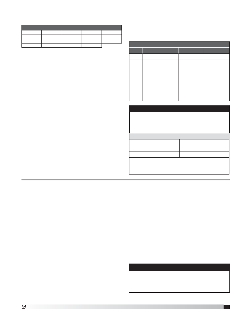
Low Voltage Harness Part Numbers
Type
Use with Motor
18 in. long
36 in. long
3-pin
311731, 310359
384431
384432
9-pin
312359, 311377,
311812, 311388,
312360, 312361,
312362, 312619,
313233, 313234,
313235, 313712,
313713, 313714,
313715, 314534,
314945
384804
384805
0-10V Analog input connection
Red
+ 0-10 VDC
White
Common*
Black
+24 VAC/DC
* Common is shared between both 24V power
and 0-10V signal.
The impedance of 0-10V circuit is 12KΩ
Factory Mounted Transformer
(Fig. 1)
A factory mounted transformer is available to
supply 24 VDC power to the motor when the
0-10V signal is by others. This transformer has
the capability to power a remote device if desired.
The power available to a remote device is 400mA
at 24 VDC. If the remote device is powered by
a different source, connect the analog output to
the 0-10V and COM terminals of the transformer.
This will pass the signal through to the motor.
WARNING
Do not connect an external 24V supply to the
transformer's control terminal labeled 24V. If the
external device providing the 0-10V signal is powered
elsewhere, this terminal can remain unused.
Troubleshooting
Motor does not operate
1. Check all wiring connections to ensure they are
correct and secure.
2. Verify that all voltages are present at the motor,
including 24V and 0-10 VDC, if applicable.
3. Make sure that the fan wheel will rotate freely and
there are no foreign objects in the wheel. If fan wheel
does not rotate freely, disconnect power from the
motor and adjust the wheel or housing until the
wheel can freely rotate. Apply power and the motor
should restart.
4. If motor has both the dial on the motor and 0-10 VDC
control option, control wiring issues can be tested
by disconnecting the control wires from the motor.
The motor should then operate using the dial on the
motor for speed control.
Motor will not reach maximum speed
1. Make sure dial is rotated full clockwise, if applicable.
2. Make sure motor is receiving 10 VDC, if applicable.
NOTE
The 9-pin connector on the motor contains 6 wires.
The red, black and white wires are used for the
external control signal and the other three are used for
factory initialization and programing.
A low voltage wiring harness is needed to supply the
0-10V signal to the motor. This harness is available from
the factory if conversion is necessary.
3. There are some motor/fan combinations
where the motor may not reach nameplate
RPM. See Max RPM table on page 10 for the
maximum motor speed for your application.
®