Herrmidifier Herrmersion RE User Manual
Page 6
Herrmersion RE
I n s t a l l a t i o n , O p e r a t i o n , & M a i n t e n a n c e M a n u a l
6
www.herrmidifier-hvac.com
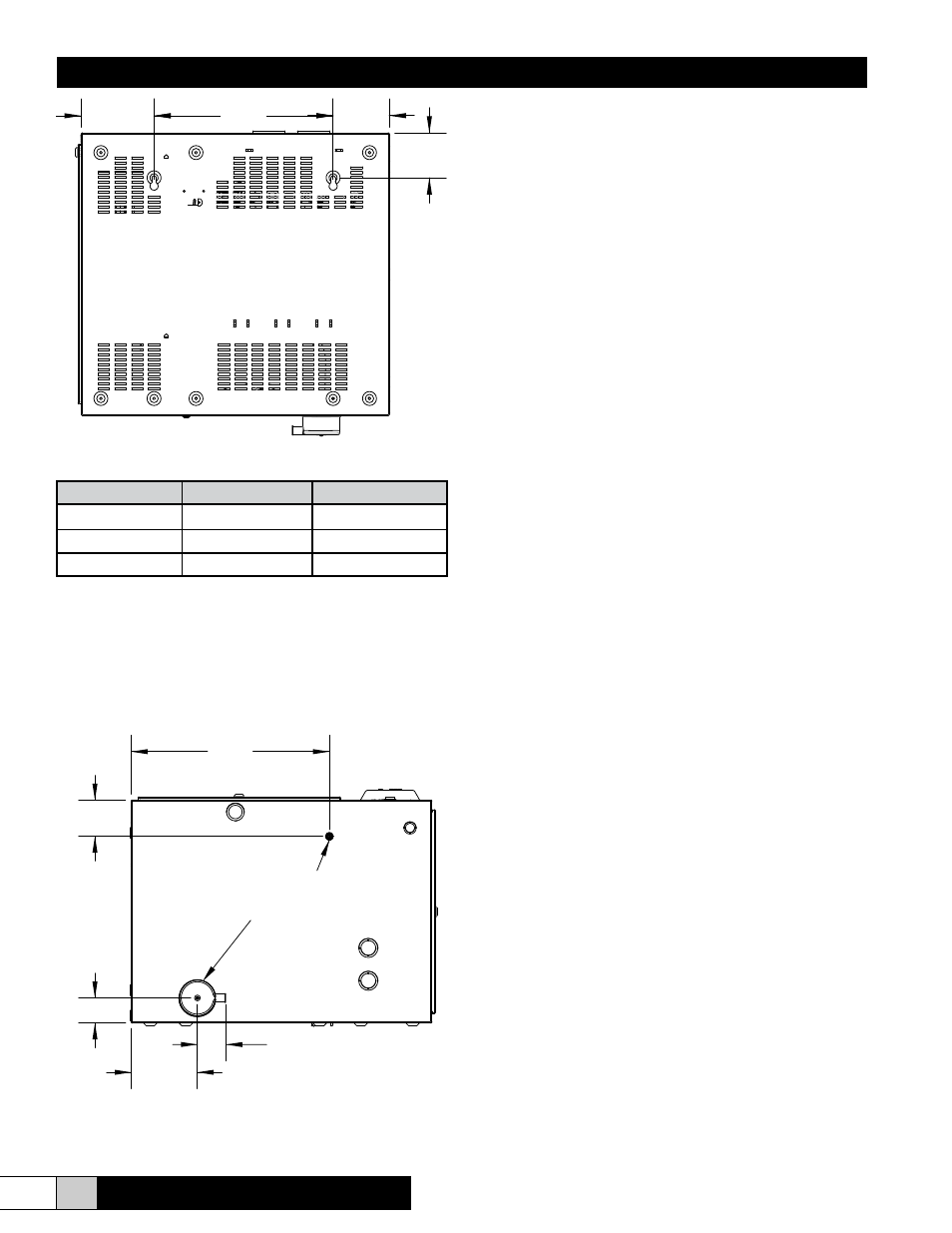
6.50
16.00
5.00
4.00
Back View (Mirror the hole pattern on mounting surface)
Model Number
Shipping Weight Operating Weight
RESX-XXX-X-30
125 lbs.
237 lbs.
RESX-XXX-X-45
128 lbs.
240 lbs.
RESX-XXX-X-90
134 lbs.
246 lbs.
“X” denotes weight independent portion of model number
PLUMBING
To make the necessary connections for water fill, drain, and
overflow/skim; the following steps are required. Refer to the
illustration below for dimensional information regarding the
fill & drain connections.
18.13
3.31
2.29
6.05
2.63 REF.
Drain Connection
Supply Connection
1. Install an external shut-off valve between the water
supply and the humidifier for ease in servicing the unit.
2. Connect the water supply to the bottom of the unit using
1/4” push-to-lock fitting. Supply water line should be
sized so that line pressure loss is minimal.
3. A drain line should be extended from the drain
connection to a sanitary waste. A minimum 1” ID copper
tube is recommended. If PVC is used, local codes
may require lower drain water temperature; enable the
drain tempering feature (see the control section of this
manual).
4. The skim/overflow connection on the front of the tank only
needs to be connected if the humidifier is being supplied
raw water containing significant mineral concentrations.
Deionized or reverse osmosis (technical waters) may be
used and do not require the use of this feature. The
skimming cycle allows floating debris to leave the tank
through the overflow drain and will reduce maintenance
intervals.
5. If using the skimmer connection, a trap must be installed
in the line so that steam can not escape from the
skimming connection during operation.
STEAM DISTRIBUTION
Herrmersion units may be used with stainless steel duct
dispersion tubes for injecting steam directly into the ductwork.
A minimum of 3 feet downstream clearance is required
for many applications; however differing psychrometric
conditions may require a greater distance. If required, consult
the factory to design a guaranteed absorption Herricane –
CS Steam Distribution System.
Mount the unit as close to the dispersion tube as possible.
Use 1.5” Type L insulated copper whenever the length of run
exceeds 20 feet. Do not exceed a 30 foot run as the capacity
of the humidifier may be decreased by as much as 15% and
the increased static pressure could cause problems with the
fill system. The maximum duct static pressure is 5” W.C.
Any insulation inside the bulk evaporation zone (inside the
ductwork) should be removed.
Steam holes in factory supplied duct dispersion tubes are
located 2” from the mounting plate and are designed for a
maximum 1” thick duct wall. Consult the factory if special
hole locations are required.
Do not install or mount standard dispersion tubes in a vertical
position or in a vertical airflow application. Special dispersion
tubes are available from the factory for installations which
require vertically mounted tubes or horizontal tubes with
vertical airflow.