LD Systems WS1000(2)(X) User Manual
Page 9
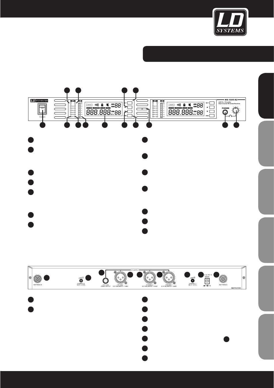
LD WS1000R2 RECEIVER:
FRONT PANEL:
BACK PANEL
1
ON/OFF SWITCH
2
ANTENNA A RECEIVER INDICATOR
Indicator lights up to signal that Antenna A is
receiving.
3
ANTENNA A RF INDICATOR
4
ANTENNA B RF INDICATOR
5
ANTENNA B RECEIVER INDICATOR
Indicator lights up to signal that Antenna B is
receiving.
6
CHANNEL 1 AUDIO AF LEVEL INDICATOR
7
CHANNEL / GROUP 1 LCD INDICATOR
Please refer to the system setup.
1
ANTENNA CONNECTOR B
2
MUTE THRESHOLD CHANNEL 2
Fine adjustment of the mute threshold value for
channel 2. Generally, it should not be necessary to
change this value. It is set correctly at the factory.
If, however, you receive interference, then you can
increase this threshold value, when the
transmitters are off, by turning the control to the
right until the RF signal LED goes out.
8
UP ARROW BUTTON
Use this button to navigate the menu.
9
SYSTEM SETUP BUTTON
Please refer to the system setup.
10
DOWN ARROW BUTTON
Use this button to navigate the menu.
11
SYNC BUTTON (ASC)
Press here to establish an infrared link
between receiver and transmitter.
12
INFRARED (IR) WINDOW
13
6.3 MM JACK HEADPHONE CONNECTION
14
HEADPHONE VOLUME
3
6.3 MM JACK OUTPUT SOCKET FOR MIX
4
XLR OUTPUT SOCKET FOR MIX
5
CHANNEL 2 XLR OUTPUT SOCKET
6
CHANNEL 1 XLR OUTPUT SOCKET
7
MUTE THRESHOLD CHANNEL 1 (SEE
2
)
8
AC POWER ADAPTER
9
ANTENNA CONNECTOR A
1
2
3
4
5
6
7
8
9
2
3
1
5
4
8
10
7
6
9
11
14
13
12
9
ENGLISH
DEUTSCH
FRANCAIS
FRANCAIS
FRANCAIS
FRANCAIS
FRANCAIS
ESP
AÑOL
IT
ALIANO
POLSKI