7 row 6 controls – Northern Airborne Technology 806 User Manual
Page 52
806 and 807 Audio Selector Panels
SM806 Installation and Operation Manual
Section 3 Rev: 1.00
Issue 4
Page 3-6
3.3.6.2
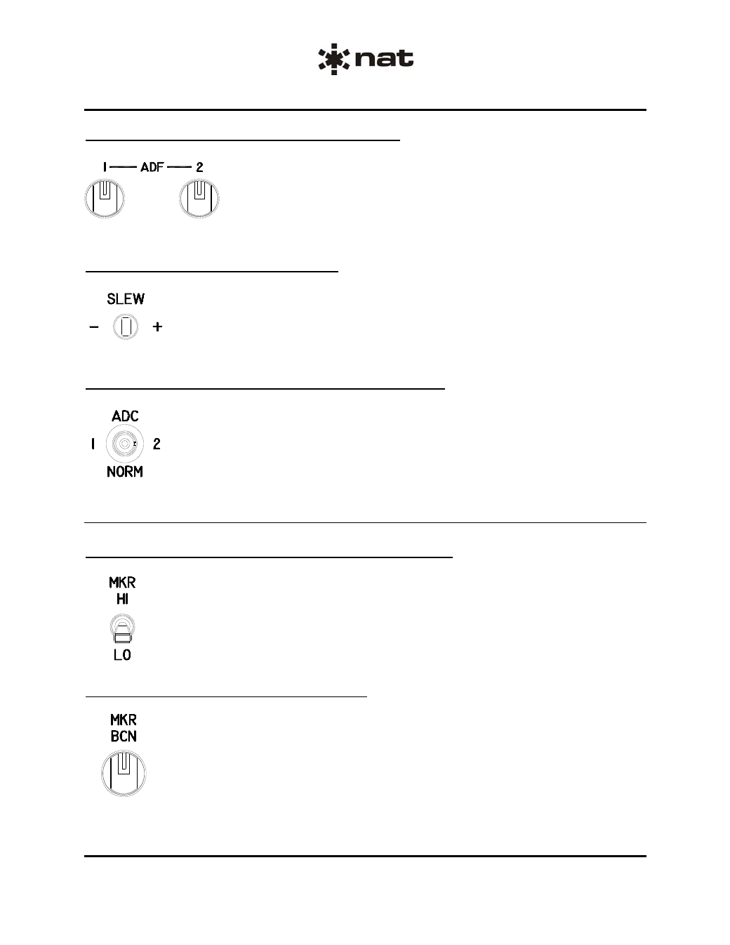
Automatic Direction Finder (ADF) 1 and 2
ADF 1 and ADF 2 are pull-push rotary switches used to control their
respective receivers.
When the control is pulled out, the relevant receiver will be selected and
when pushed in, it will be deselected. The rotary function of the switch is
used to adjust the volume.
3.3.6.3
Gyro Slew Switch (SLEW -/+)
The Gyro Slew switch is a momentary, 3-position centre-off toggle switch that allows
slewing when the AHRS is in DG mode.
3.3.6.4
ADC Switch (ADC 1, 2, NORM) – Model 806 only
The Air Data Computer (ADC) switch is a 3-position centre-off locking toggle switch used
to select the display method for ADC data.
In position 1, ADC1 is the source for data displayed on PFD1 & PFD2.
In position 2, ADC2 is the source for data displayed on PFD1 & PFD2.
3.3.7
Row 6 Controls
3.3.7.1
Marker Sensitivity Switch (MKR) – Model 806 only
The Marker Sensitivity switch is a 2-position toggle switch that sets the sensitivity of the
marker beacon to hi or lo.
3.3.7.2
Marker Beacon Switch (MKR BCN)
The Marker Beacon switch is a pull-push rotary switch used to control the 2 marker
beacon receivers.
When the control is pulled out, the relevant receiver will be selected and when pushed in,
it will be deselected. The rotary function of the switch is used to adjust the Marker
Beacon volume.
ENG-FORM: 806-0111.DOT
CONFIDENTIAL AND PROPRIETARY TO NORTHERN AIRBORNE TECHNOLOGY LTD.