Olson Technology CAN User Manual
Page 18
025-000570 Rev. X7
www.olsontech.com
18
TRANSMITTER & RECEIVER RF LEVEL DETECTOR PERFORMANCE
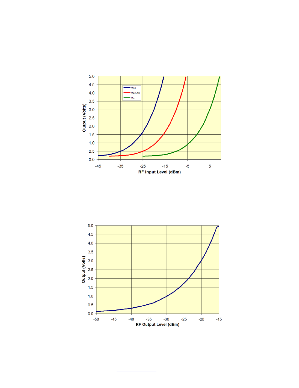
Figures 17 and 18 show behavior of the transmitter and receiver RF Level Detectors.
Figure 17 shows the behavior of the transmitter RF Level Detector at Maximum Gain (25dB),
Maximum-10 Gain (15dB) and Minimum Gain (0dB). To use the chart, first determine the
transmitter gain and measure the voltage out of the RF Level Detector. Then use the chart to
estimate the total RF Level in to the transmitter.
Figure 17 - Transmitter RF Level Detector Behavior
Figure 18 shows the behavior of the receiver RF Level Detector for a normal sensitivity
PIN-based receiver. To use the chart, measure the voltage out of the RF Level Detector, then
use the chart to estimate the total RF Level out of the receiver. Contact the factory for the
response of a high-sensitivity APD-based receiver.
Figure 18 - Receiver RF Level Detector Behavior