Olson Technology CAN User Manual
Page 9
025-000570 Rev. X7
www.olsontech.com
9
POWER SUPPLY DESCRIPTION
The Model OTAPS Advanced L-Band Power Supply offers additional functionality to the sys-
tem. The power supply incorporates a selectable +13/+17V power supply option to power the
LNB for each transmitter. A selectable 22kHz tone is also designed in. The power supply ac-
commodates 90-250Volts, 47-63Hz AC (Model OTAPS-4000-AC) input. One power supply will
power up to five transmitters or receivers in any combination. An LED indicator gives a posi-
tive indication that the system is being powered.
The OTAPS power supply ships with a North American AC power cord and five (5) DIN cables
each 24” long.
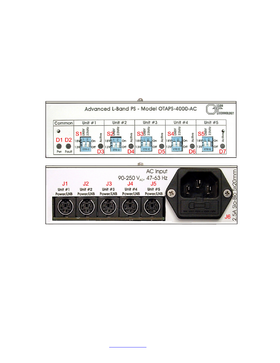
Figure 4 - Front and Rear View of Advanced L-Band Power Supply
POWER SUPPLY CONTROLS OVERVIEW
On the front of the power supply, D1 indicates that the power supply is powered and operating
normally. D2 indicates if there is a fault with any of the units connected to the power supply.
LED’s D3 through D7 indicate if Units 1 through 5 are connected. Switches S1 through S5 are
used to select +13 Volts or +17 Volts for each unit and also turn on or off the 22kHz tone.
On the rear of the unit, connectors J1 through J5 are used to power up to five transmitters or
receivers. Connector J6 is the AC input. It also contains the AC fuses for the unit. See Figure 7
for details.