Olson Technology CAN User Manual
Page 8
025-000570 Rev. X7
www.olsontech.com
8
Level detector (discussed later) still functions as though the receiver is not muted.
J1 & J3 allow easy measurement of the transmitter optical output power using a Digital Volt
Meter (DVM). J1 is a ground. J3 gives an indication of the Optical Input Power. The scale
factor is 1.0V/mW. J2 is the optical input. D1 indicates the RF Output Power level. D2 indi-
cates the input RF Level. Figure 2 indicates the thresholds at which D2 will switch. D2 will be
yellow if the RF level is below the low threshold, red if the RF level is above the high threshold
and green if the RF level is between the low and high thresholds. For most applications, if D2
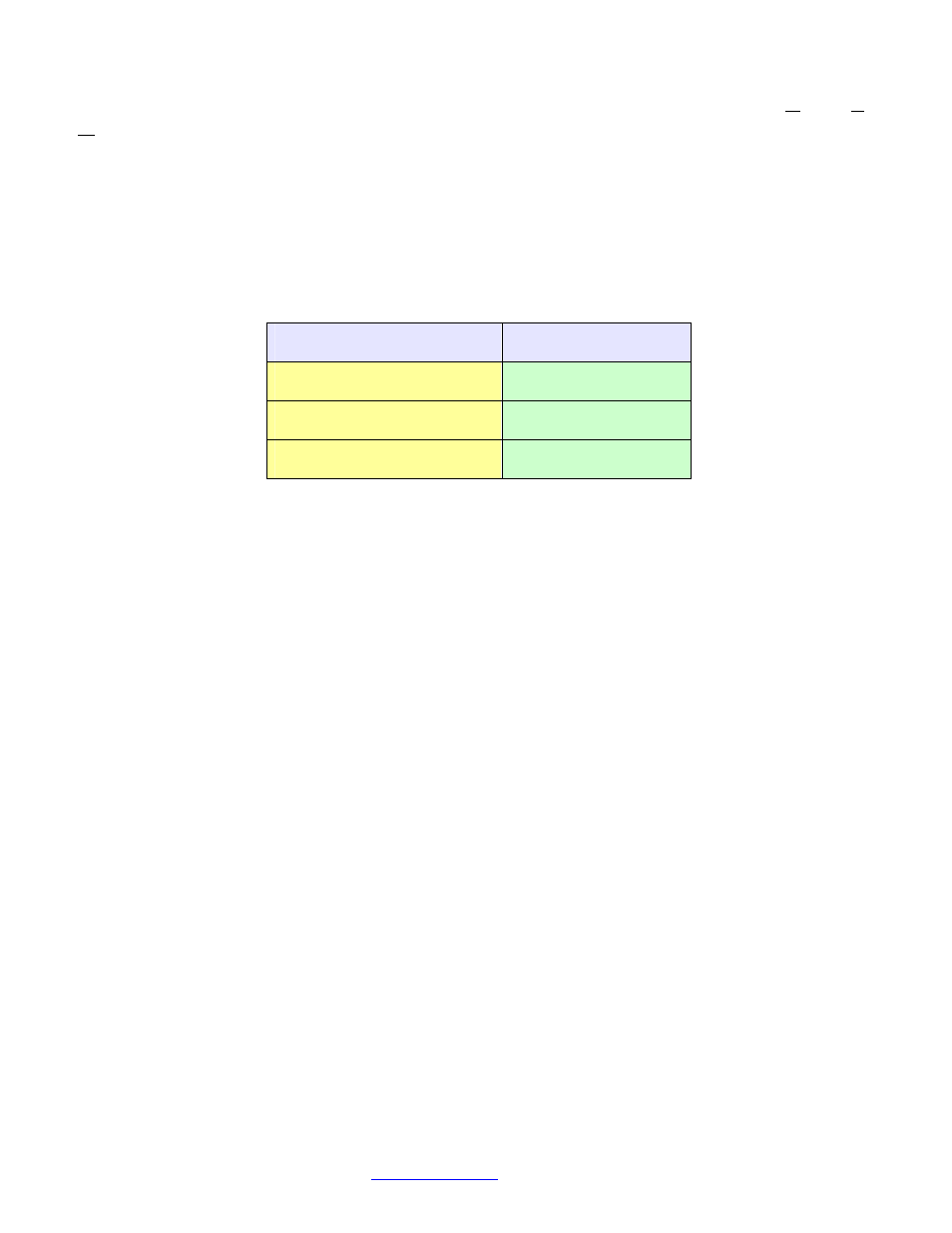
is green, then the RF level is in the optimum range. Table 1 shows the behavior of the Re-
ceiver D2 LED. J4 is the RF Output. It is a high-frequency F-Type Female (75Ω) Connector.
Table 1 - Receiver D2 LED Behavior
RF Output Level
D2 LED Color
<-37dBm
Yellow
≥-37dBm and ≤ -22dBm
Green
>-22dBm
Red
Note: This holds true even if the Receiver output is Muted
On the rear of the transmitter, connector J5 is used to connect to the OTAPS Advanced
L-Band Power Supply. Connector J6 is for unit power voltage input via an “F” connector.
Connector J7 provides various status outputs. These will be discussed later in this document.
See Figure 6.