ONICON FB-3500 Series User Manual
Page 10
11451 Belcher Road South, Largo, FL 33773 • USA • Tel +1 (727) 447-6140 • Fax (727) 442-5699 • [email protected]
FB-3500 Bi-Directional Insertion Electromagnetic Flow Meter Manual 05/14 - 0718-3
Page 10
SECTION 3.0: INSTALLATION, REMOVAL AND ADJUSTMENT
WARNING
Insertion flow meters may be installed in pipes which are under high pressure. Accidents with
these systems can cause serious injury or death. Only persons experienced with high pressure
systems and related knowledge in the heating, cooling and fluid metering fields should attempt
to install, adjust, or remove the flow meter. Please read all instructions before attempting to
insert or remove a flow meter.
!
ONICON will be happy to assist with technical recommendations and to provide guidance by
telephone or e-mail. On-site field engineering, installation and service is also available at additional cost.
3.1 INSTALLATION SITE SELECTION
Install the flow meter where it will be accessible for personnel to perform necessary periodic
maintenance. The clearance required for installation is typically 30”- 40” from the pipe wall to
the nearest obstruction above the valve assembly. This clearance dimension will increase with
large diameter pipes. The environment should be free of corrosive liquids/fumes, temperature
extremes and heavy vibration. The following diagrams should be used as a guide to the proper
location for installing the meter.
3.1.1 General Site Selection Guidelines
GENERAL PRACTICES:
1.
For best results, install the flow meter in a straight run of pipe, free of bends, tees,
valves, transitions and obstructions.
2.
Straight run recommendations vary based on the nature of the upstream obstruction.
See the table below for guidelines in determining upstream straight run
recommendations based on the nature of the obstruction. Please note that depending
upon specific location details, more or less straight run may be required to produce a
satisfactory flow profile.
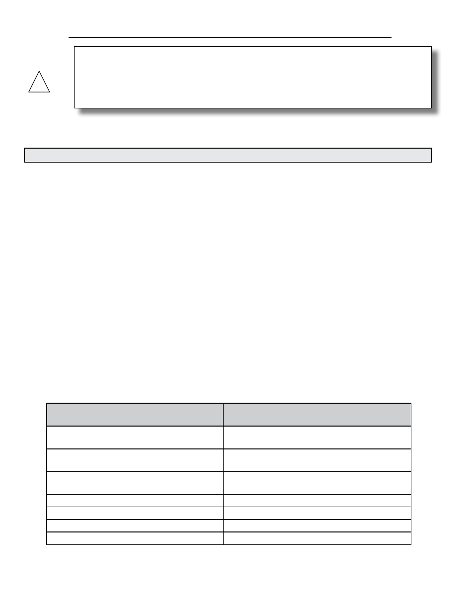
For 3” and larger pipe diameters
Obstruction on either side of meter
Straight run distance recommended
between meter and obstruction
Single bend preceded by ≥ 9 diameters of
straight pipe
10 Diameters
Pipe size reduction / expansion in straight
pipe run
10 Diameters
Single bend preceded by ≤ 9 diameters of
straight pipe
15 Diameters
Outflowing tee / pump outflow
20 Diameters
Multiple bends out of plane
30 Diameters
Inflowing tee
30 Diameters
Control / modulating valve
30 Diameters