Caution, 1 signal and power wiring connections – ONICON FB-3500 Series User Manual
Page 21
11451 Belcher Road South, Largo, FL 33773 • USA • Tel +1 (727) 447-6140 • Fax (727) 442-5699 • [email protected]
FB-3500 Bi-Directional Insertion Electromagnetic Flow Meter Manual 05/14 - 0718-3
Page 21
CAUTION
Failure to provide a proper earth connection to the meter may result in excessive electrical
noise that will interfere with the operation of the meter.
!
Wire Color
Description
Notes
Red
(+) Supply voltage: 24±4 VDC @ 250 mA or 24±4 VAC,
60 Hz, 6 VAC
Connect to power supply (+): DC (+) or
AC (line)
Black
(-) Isolated supply voltage common
Connect to power supply (-): DC (-) or
AC (neutral)
Green / Yellow
Earth ground connection
Required to operate the meter
Green
(+) Isolated frequency output
Required when connecting to ONICON
display or BTU meter
Yellow
(-) Frequency output common
Blue
(+) Isolated analog output
Configurable as a 4-20 mA, 0-10 V or
0-5 V output
Brown
(-) Isolated analog output common
Gray
Forward flow, scaled output, isolated dry contact
Scalable dry contact pulse output for
forward flow totalization
Violet
Gray / Black
Reverse flow, scaled output, isolated dry contact
Scalable dry contact pulse output for
reverse flow totalization
Violet / Black
Orange / Black
Flow direction indicator, isolated dry contact
Contact closed when flow is in direction
of arrow on meter
White / Black
Diagnostic Signals
Orange
Master alarm, isolated dry contact
Dry contact closure signal indicating
fault condition
White
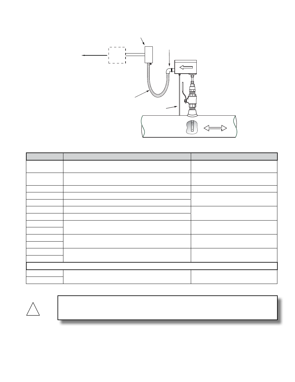
3.5.1 Signal and Power Wiring Connections
½" FNPT
conduit connection
Insertion depth
gage provided
with each meter
FLOW
Customer provided
conduit and adapters
Output signal(s)
to control
system
ONICON
Display or
BTU Meter
(Optional)
Allow enough slack
in the flexible conduit
to permit the meter
to be removed
from the valve.