ONICON F-3100 Series User Manual
Page 35
11451 Belcher Road South, Largo, FL 33773 • USA • Tel +1 (727) 447-6140 • Fax (727) 442-5699 • [email protected]
F-3100 Flow Meter Manual 06/14 - 0670-7
Page
35
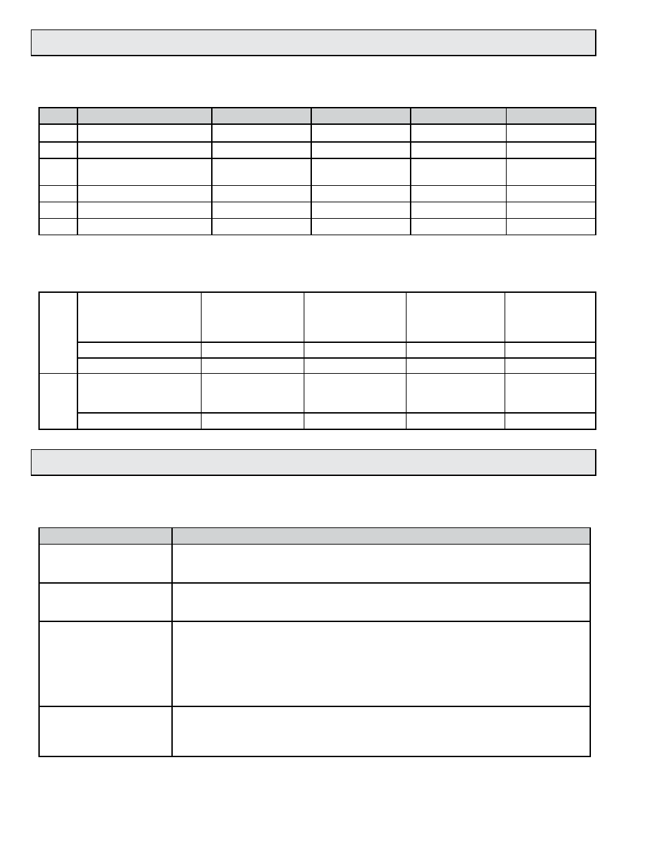
4.4 START-UP AND COMMISSIONING WORKSHEET
Please read all installation instructions carefully prior to proceeding with these steps. Use the
following worksheet for checking off the commissioning steps and recording measured values.
STEP
TEST/MEASUREMENT
S/N: _________
S/N: ________
S/N: ________
S/N: _________
1.
Meter location:
2.
Control system programming:
3.
Match display or Btu meter
serial # (S/N) if ordered:
4.
Signal connections verified:
5.
Supply voltage verified:
6.
Connect power:
The following steps require flow in the pipe. Flow signal readings should be taken while holding
the flow rate constant if possible. Otherwise, take the various output readings as quickly as possible.
10.
Analog or binary outputs
4-20 mA signal:
________ mA
________ mA
________ mA
________ mA
scaled output interval
___________
___________
___________
___________
Calculated flow rate:
_______ GPM
_______ GPM
_______ GPM
_______ GPM
11
Flow rates displayed on
meter display:
_______ GPM
_______ GPM
_______ GPM
_______ GPM
control system:
_______ GPM
_______ GPM
_______ GPM
_______ GPM
4.5 TROUBLESHOOTING GUIDE
NOTE: Also refer to the START-UP AND COMMISSIONING GUIDE located on the preceeding
pages.
REPORTED PROBLEM
POSSIBLE SOLUTIONS
No signal
• Verify correct wiring to control system (See wiring diagram.)
• Check display for alarm messages. Verify that the pipe is full.
• Verify that the sensor body and transmitter are both connected to earth ground.
Reading is too high or low
• Verify correct wiring to control system (see wiring diagram).
• Confirm that the output signals are consistent (frequency vs. analog, etc).
• Confirm that the control system is programmed for correct flow range or scale factor.
Analog signal seems high or
low and does not correspond
to frequency output
Check for ground loop or offset voltage:
• Verify that the sensor body and transmitter are both connected to earth ground.
• Disconnect analog signal input from control system and measure analog outputs directly from
the flow meter.
• Re-connect signal input to control system and measure the analog signals again.
• Any difference between these readings indicates a potential ground loop or offset voltage.
• Please contact ONICON for further assistance.
Control system displays
flow rate, but no flow rate is
indicated on the local
display module or Btu meter
• Verify that all of the wires from the flow meter are connected to the display module or Btu
meter.
• The frequency output wire (green) must be connected for any ONICON display or Btu meter.