ONICON F-3100 Series User Manual
Page 7
11451 Belcher Road South, Largo, FL 33773 • USA • Tel +1 (727) 447-6140 • Fax (727) 442-5699 • [email protected]
F-3100 Flow Meter Manual 06/14 - 0670-7
Page
7
SECTION 1.0: INTRODUCTION
1.1 PURPOSE OF THIS GUIDE
The purpose of this guide is to provide installation and commissioning procedures and basic
operating instructions for the F-3100 Inline Electromagnetic Flow Meter.
1.2 PRINCIPLE OF OPERATION
The operating principles of ONICON F-3100 Inline Electromagnetic Flow Meters are based
on Faraday’s Law of Electromagnetic Induction. Faraday’s Law states that a voltage will be
induced in a conductor (water or other conductive liquid) when it passes through a magnetic field
(generated by the meter), and the induced voltage will be directly proportional to the velocity of
the conductor. By placing electrodes on opposite sides of the flow tube, it is possible to accurately
measure the induced voltage and determine the corresponding velocity of the flowing liquid.
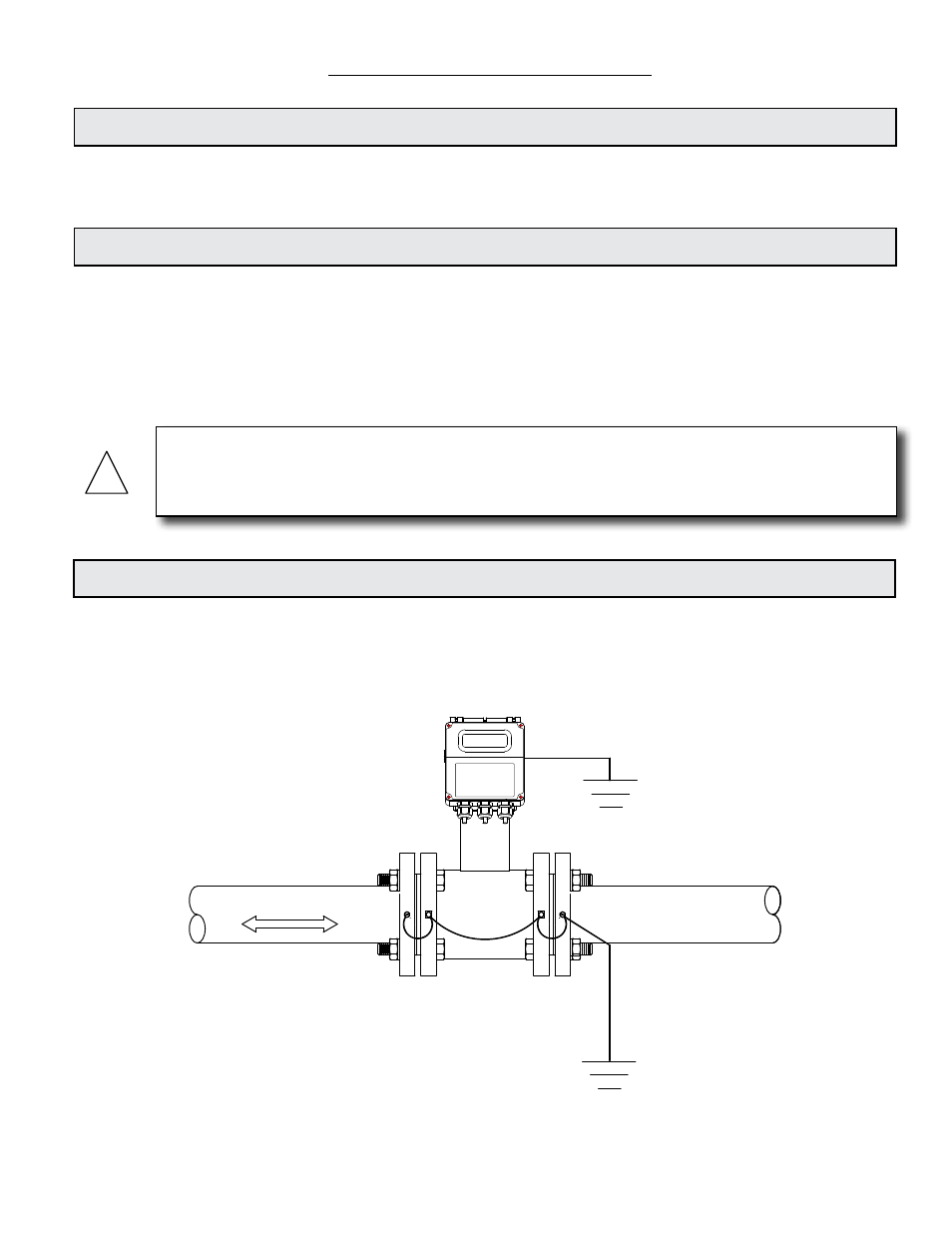
1.3 TYPICAL FLOW METER INSTALLATION
ONICON’S F-3100 Series Inline Magnetic Flow Meters are suitable for volumetric flow
measurement of electrically conductive liquids in a wide variety of applications including
bi-directional applications.
WARNING
Only qualified service personnel should attempt to install or service this product. Serious injury
may result from the improper installation or use of this product.
!
Flow direction
INSTALLATION IN STEEL (CONDUCTIVE) PIPE
F-3000 Series Mating Flange Grounding Kit Instructions
Note 1.
Using a #21 (0.159”) drill bit, drill a ½” deep hole in edge of each mating flange. Tap each hole using a 10-32 tap.
Secure the provided ring connectors and grounding wires to the flanges using the provided green grounding screws.
(Alternate method: Weld 10-32 studs (not provided) to the flange faces and attach ring connectors with 10-32 nuts (not provided.)
Note 2.
Provide a ground connection at the input power terminals inside the transmitter enclosure.
Note 3.
Provide a quality earth ground connection to the meter.
From best to worst, grounding options include:
1. Earth grounding rod driven into the soil.
2. Earth wire connected directly to the building electrical service panel.
3. Earth wire connection inside an electrical outlet near the meter.