Alarms – ONICON F-3100 Series User Manual
Page 36
11451 Belcher Road South, Largo, FL 33773 • USA • Tel +1 (727) 447-6140 • Fax (727) 442-5699 • [email protected]
F-3100 Flow Meter Manual 06/14 - 0670-7
Page
36
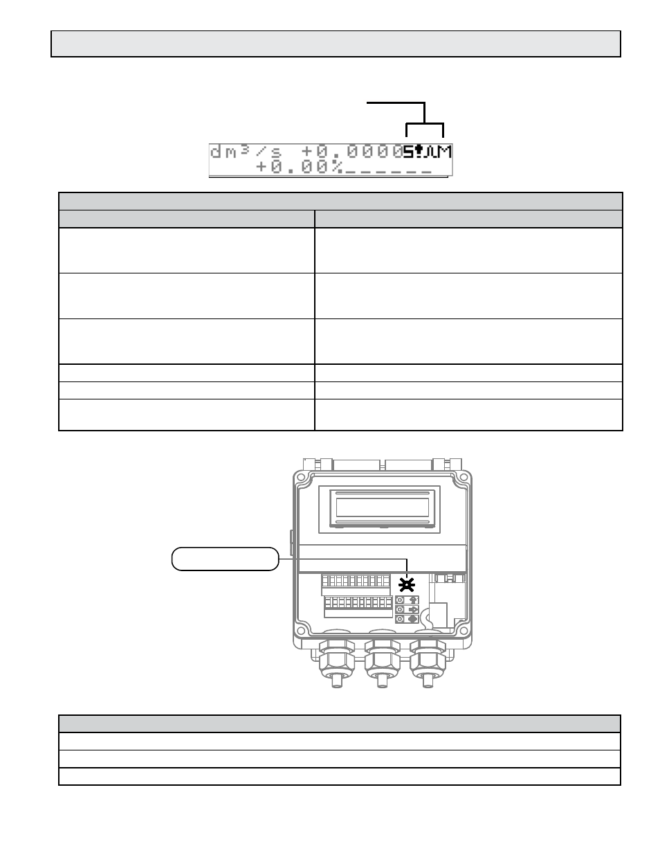
4.6 ALARM INTERPRETATION AND STATUS LED’s
Alarm Indicators
Symbol
Description
M
When activated, this symbol indicates flow in excess
of the set point.
Range: 0-125% of full scale
m
When activated, this symbol indicates flow below the
set point.
Range: 0-125% of full scale
!
• Open coil connection
• Signal error
• When activated, indicates empty pipe.
C
Calibration running
S
Transmitter in simulated output mode
W
Pulse output saturated (change pulse rate or
duration)
ALARMS
1
2
3
4
5
6
7
8
9
10
11
12
13
14
15
16
17
18
19
20
INTERPRETATION ALARMS
ALARM
M
Alarm max activated
m
Alarm min activated
!
- Interruption coils circuit
- Segnal error
- Empty pipe
C
Calibration running
S
Simulation
Pulse output saturation (reduce
TIME PULSE )
ALARMS
LED
LED INTERPRETATION
PERMANENT LIGHT: initialisation
FLASHING LIGHT ( 1 sec.): normal function
FLASHING LIGHT (<1 SEC.): alarm on
The LED signals the real alarm status only if the display visualizes one of
the visualization pages suitable to page 17
DESCRIPTION
Status LED
Continuously ON: Initialization of firmware
Flashing LED: (1 second rate): Normal operation
Flashing LED: (<1 second rate): Alarm condition