ONICON D-1400 User Manual
Page 7
11451 Belcher Road South, Largo, FL 33773 • USA • Tel +1 (727) 447-6140 • Fax (727) 442-5699 • [email protected]
D-1400 Portable Metereing System Manual 05/14 - 0722-2
Page 7
1.4 ADDITIONAL REQUIRED HARDWARE
Flow Meter
ONICON offers a wide variety of flow meters to satisfy most liquid, gas and steam
metering applications. Please refer to ONICON’s flow meter literature, or consult
ONICON or your local representative for help in selecting the flow meter that will best
fit your requirements.
1.5 WORKING ENVIRONMENT
The D-100 was designed for installation and use in typical industrial environments that are
free of corrosive liquids and fumes, direct liquid exposure, heavy condensation, temperature
extremes, direct sunlight, and vibrations. The operating ambient air temperature range is -20° F
to 140° F. Electrical power should be relatively clean, free of high frequency noise, large voltage
transients, and protected from power surges and brown-outs.
1.6 WARRANTY & SERIAL NUMBER
Warranty
ONICON’s 2-year “No-fault” warranty reduces start-up costs by extending coverage for
incidental damage during installation. Certain exclusions apply. Please refer to ONICON’s
Conditions of Sale for details.
Serial Number
The serial number of your D-100 is located outside and inside the enclosure. Also located
inside the enclosure is a label with the serial number of the associated ONICON flow
meter or sensor your D-100 was intended to be used with. The serial numbers are unique
identifiers that you should have available when contacting ONICON for assistance
regarding the installation or use of this product.
SECTION: 2.0 SYSTEM OPERATION AND SET-UP
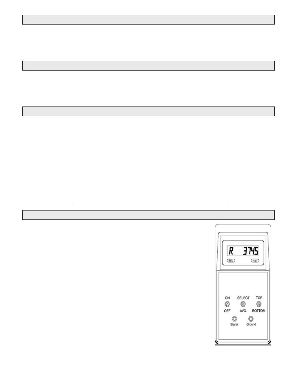
2.1 SYSTEM OPERATION
The D-1401 and D-1402 Display Module LCD display shows the flow
rate as a number representing the frequency output signal, in Hertz,
from the flow meter.
The D-1401 Display Module shows the frequency output signal of the
single turbine from the F-1100.
The D-1402 Display Module shows the averaged output from both
turbines. This system also has the capability of displaying the
individual output from the top or bottom turbine by using the
selection switches on the Display Module.
This frequency output is then converted to gallons per minute for the
pipe size being measured via the laminated conversion chart included
with the system.
Please contact ONICON to obtain conversion factors for any pipe
sizes not listed on the chart, or if you require a flow rate unit of
measure other than gallons or liters.