OnLine Power Power Wave 1 User Manual
Page 27
6005-085 Rev B
26
The UPS communicates with the computer by sending an RS-232 data streams to one of the
serial ports, which allows the user to monitor the following parameters:
Input Voltage:
Indicates the present input
voltage to the UPS system when
power is present.
Output Voltage: Indicates the present output
voltage of the UPS.
Battery Voltage: Indicates the present DC voltage
of the UPS battery.
Temperature:
Indicates the actual temperature
inside the UPS.
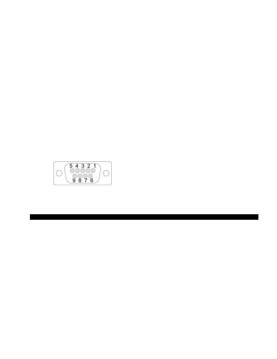
9.2 DB9 PIN Assignment
PIN 2: RS232 RXD
PIN 3: RS232 TXD
PIN 5: GND
The other pins have no function
DB9 INTERFACE CONNECTOR
10. Options
10.1 Auxiliary Norm ON C.B options,1pole, 20amp (maximum of 12 each)
10.2 Auxiliary Norm OFF or Norm ON W/ delay C.B options, 1pole, 20amp (maximum of 12 each)
10.3 MBS ( Maintenance By-pass Switch
– manual)
10.4 Auxiliary TVSS
10.5 Floor Mounting Brackets
10.6 Communication Interface (RS232, USB)
10.7 SNMP/WEB Card or AS400C W/ Relay Card
10.8 Remote Status Panel (Remote Monitor)
10.9 AS400 Relay Card is used to provide potential free relay contact interface for those industrial control
applications that require dry contact signals.