Ò³ãæ 27, 2 wiring – Onwa Marine Electronics KAP-866 User Manual
Page 27
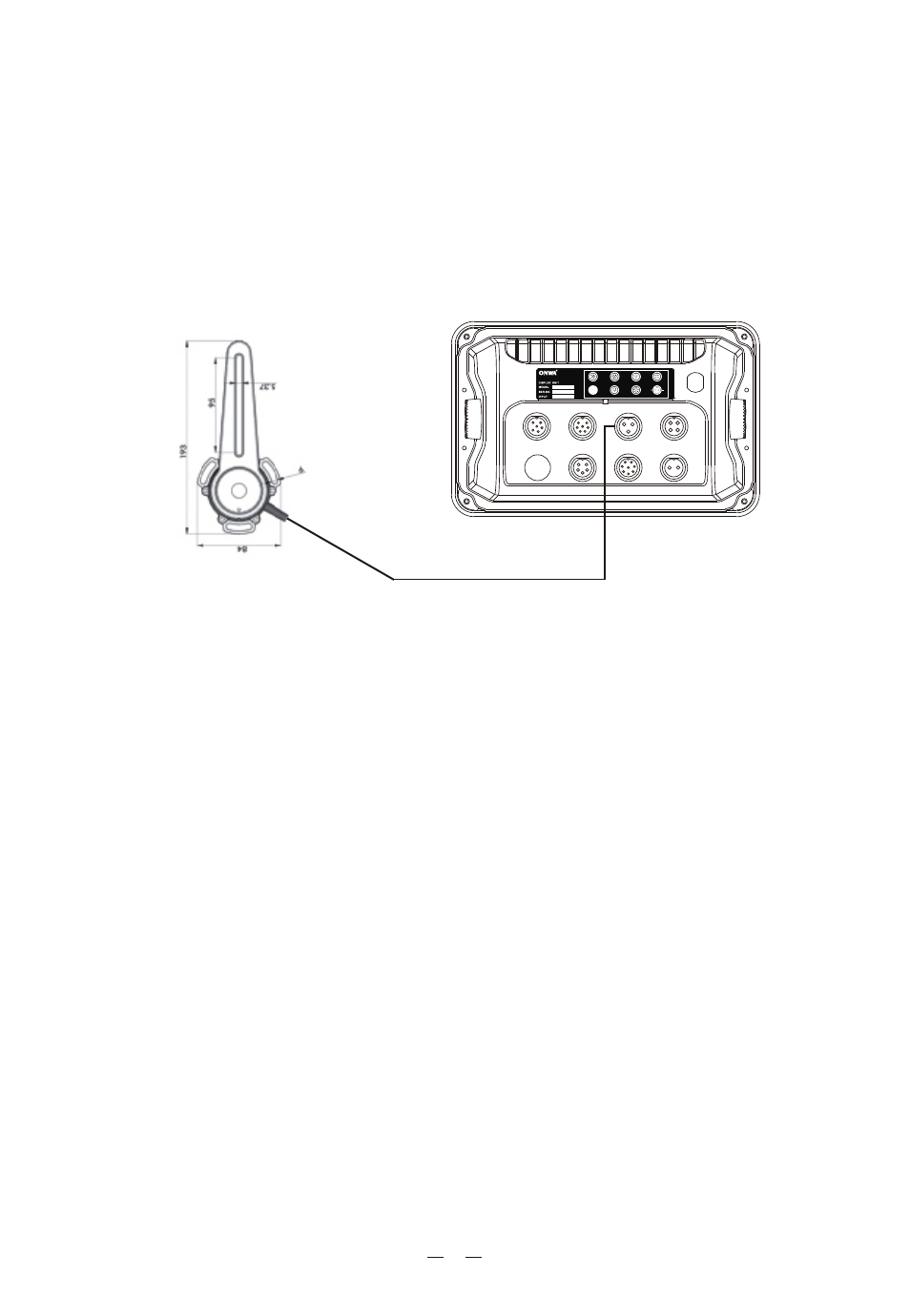
3.2.2 Wiring
Connect the cable of rudder feedback unit to the 3 pins socket on the rear panel
of KAP-866. To check the wirng of the rudder feedback unit by steer the rudder
to either side (Port or Starboard), see whether the rudder angle indication on
KAP-866 goes to corresponding direction. If the rudder angle indication on
KAP-866 goes to reverse direction against the applied rudder then you need to
reverse the wiring of RED and BLACK.
After installation of the feedback unit is complete and the linkage is fitted,
have the steering of the vessel turned lock to lock and ensure:
a)The direction (port or starboard) indicated on the top of the RFU is correct.
b)No undue mechanical strain is placed on the rudder feedback or linkage.
NOTE: THE AUTOPILOT WILL NOT FUNCTION CORRECTLY IF A
RUDDER FEEDBACK IS NOT FITTED, OR IF THE FEEDBACK IS
FAULTY OR INCORRECTLY ADJUSTED.
NOTE: THE RUDDER FEEDBACK UNIT IS FACTORY ALIGNED. THE
ARM SHOULD NOT BE REMOVED OR LOOSENED UNNECESSARILY.
IF ARM IS LOOSENED OR REMOVED, VOLTAGE ALIGNMENT SHOULD
BE CHECKED BEFORE USING THE AUTOPILOT. THIS MUST BE DONE
BY A COMPETENT TECHNICIAN.
Terminal 5V : + 5 volts Red
Terminal Rud : Signal Yellow
Terminal GND : GND Black
22
AUTOPILOT
COMPASS
REMOTE
RUDDER
MOTOR
ALA/RUDM
NMEA I/O
POWER IN