Troubleshooting, Outputs force, Modular service tool sd 12 – Orion System Modular Service Tool SD User Manual
Page 12
Zone
Zone
TROUBLESHOOTING
Modular Service Tool SD
12
Outputs Force
Outputs Force
Outputs Force settings are available for testing or troubleshooting the
system. These Force settings can only be accessed and programmed
from the Modular Service Tool. The System Manager does not allow
for programming of this function.
CAUTION: The Outputs Force settings should only be applied
by qualifi ed service personnel. Serious damage to
the HVAC unit could result from improper use of
these Outputs Force settings.
To access the Outputs Force settings, simply press the
<BALANCE -
TEST>
button on the Modular Service Tool. You will then see the Unit
Selection Screen. Enter the unit ID of the Unit Controller you wish to
access and press
<ENTER>
. Once communication is established, *00*
at the bottom of the screen will go away. Then
press
<
>
. You will
then see the screen shown below. Press
<ENTER>
to save entered data
and
press
<
>
to scroll through the screens.
NOTE:
If the *00* remains, it indicates a communication failure
to the controller.
NOTE:
The Outputs Force settings are only available for the Unit
Controllers. They are not supported for the VAV/Zone
Controllers or other Add-on controllers.
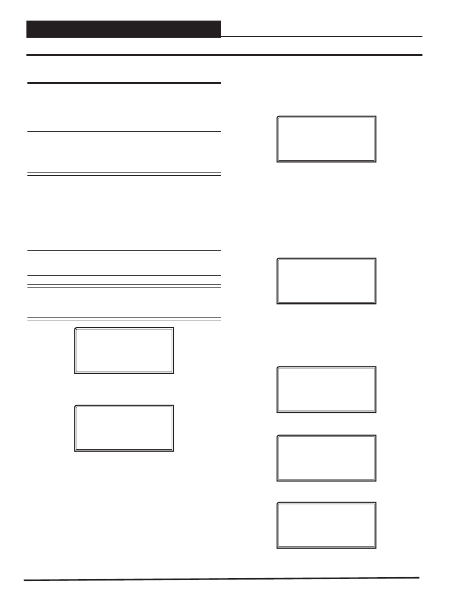
Outputs Force
Para Blocks
Save / Load / Copy
Place the cursor on Outputs Force and press
<ENTER>
to access the
Outputs Force Screen.
Supply Fan Override
Auto
Use < Or > To Change
The fi rst Outputs Force Screen allows the AHU fan relay to be set for
Auto, Force On, or Force Off. The default setting is Auto. After you
complete all troubleshooting or testing procedures, all relays should be
changed back to this setting. The Force On setting will force the relay
to the ON (energized) position. The Force Off selection will force the
relay to the OFF (de-energized) position.
The next screen displays the Relay Overrides for Relay 2. After press-
ing
<ENTER>
to save any changes, press
<
>
to have the next relay
displayed. All 20 Relay Override Screens (including the AHU fan relay)
are available by pressing
<
>
after each setting is saved by pressing
<ENTER>
.
Relay Overrides
Relay 2 Override
Auto
Use < Or > To Change
After the screen for relay 21 or 23 (23 for VCB-X) is displayed, the fi rst
Analog Output Override Screen will be displayed. For VCC-X, after
Relay 8, EM1 Relays 1-5 will display and then 12 Relay Bd Relays
1-12 will display.
VCM-X, VCM & RNE Controllers
Analog Output 1 Screen
Economizer Overrides
Analog Output #1
Override Volts: -1.0
[-1.0=Auto]
The default setting for normal operation is -1.0 volts. Voltages between
0 to 10.0 can be set for any of the Analog Output Overrides. Press
<ENTER>
after making a setting change and then press
<
>
and the
next Analog Output Override Screen will be displayed.
Analog Output 2 Screen
Supply VFD Override
Analog Output #2
Override Volts: -1.0
[-1.0=Auto]
Analog Output 3 Screen
Exhaust VFD Override
Analog Output #3
Override Volts: -1.0
[-1.0=Auto]
Analog Output 4 Screen
Mod Heating Override
Analog Output #4
Override Volts: -1.0
[-1.0=Auto]